|
| |
|
In the Yugoslav People's Army, HF-band radio devices were used for tactical, operational, and strategic radio communications. SSB and CW modes were most commonly used, with AM less frequently. RTTY (radioteletype — radio-teleprinter) mode dominated for radio communications between higher-level units and commands. Transmitter output power ranged from 1W–10W for short and medium-range communications, to several kW for long-range communications.
HF (high frequency) or shortwave comprises frequencies from 3 MHz to 30 MHz. A characteristic of this band is that electromagnetic radiation is divided into a ground wave and a sky wave component. The ground wave enables communications at short distances because, like VHF waves, it requires "line of sight".
The other, far more interesting, sky wave component bends and is partly reflected off the Earth's ionosphere, and when returned this way, it can enable communications with participants on the other side of the world. On the other hand, these links are very easily intercepted and jammed. Jamming can be unintentional (various natural and artificial sources of radio interference), or deliberate by the adversary using high-power radio jammers. This often resulted in communications not being maintainable at the required time.
For these reasons, "major" armies have almost entirely abandoned this band and moved to satellite communications, which are more reliable but also much more expensive. However, this band is still used to organize backup communications channels in situations where, for some reason, VHF, UHF, and SHF communications are not functioning. Radio telegraphy has also remained the primary mode of operation on these backup channels.
|
| |
Tabular overview of HF radio devices |
(clicking on the device code allows you to navigate quickly within the page) |
| |
DESIGNATION
|
TYPE
|
FREQUENCY RANGE
|
OPERATING MODES
|
TX POWER
|
ORIGIN
|
| |
|
RX |
0.097MHz-7.095MHz |
CW, AM |
- |
Germany |
| |
|
RX |
0.5-12.5MHz |
CW, SSB |
- |
Yugoslavia |
| |
RB, RBM, RBM-1 and RBM-5 |
TX/RX |
1,5-6MHz (1,75-6MHz) |
CW, AM |
1W (5W) |
SSSR (Russia) |
| |
|
TX/RX |
3,8-5,8MHz |
CW, AM |
24W |
SAD (USA) |
| |
|
TX/RX |
2-12MHz |
CW, AM |
15W |
USA |
| |
|
TX/RX |
2-12MHz |
CW, AM |
15W |
Yugoslavia |
| |
|
RX |
2-12MHz |
CW, AM |
- |
Yugoslavia |
| |
|
TX/RX |
2.8-4.99MHz |
CW, AM |
90W |
SSSR (Russia) |
| |
|
TX/RX |
1.5-10.99MHz |
CW, AM, SSB |
40W |
SSSR (Russia) |
| |
|
RX |
1-15MHz |
CW, AM |
- |
SSSR (Russia) |
| |
Collins 51S-1 |
RX |
0,2-30MHz |
CW,AM,SSB |
- |
SAD (USA) |
| |
|
TX/RX |
2-12MHz |
CW, AM, SSB |
15W |
Yugoslavia |
| |
|
RX |
2-12MHz |
CW, AM, SSB |
- |
Yugoslavia |
| |
|
TX/RX |
2-29.9999MHz |
CW, AM, SSB |
30W |
Great Britain |
| |
|
TX/RX |
2-29.9999MHz |
CW, AM, SSB |
20W |
Yugoslavia |
| |
|
RX |
0.5-29.9999MHz |
CW, AM, SSB |
- |
Yugoslavia |
|
| |
Description of HF radio devices |
 |
HF radio-receiver TORN Eb
In the website's introduction we stated that we would not describe communications devices from before and during World War II; however, this HF radio-receiver, produced in Germany in 1936, deserves to appear on this page. The receiver was mass-produced for the German army, and by 1945 it had undergone several modifications. (The device  described here represents the 1943 version). It entered the Yugoslav army's arsenal as war booty in 1945, which the victors had to emphasize during the first overhaul in domestic workshops by inscribing on the side: "captured 16962 devices". In the JA, the receiver was used in conjunction with a transmitter or independently. It was removed from JNA inventory in the 1950s. described here represents the 1943 version). It entered the Yugoslav army's arsenal as war booty in 1945, which the victors had to emphasize during the first overhaul in domestic workshops by inscribing on the side: "captured 16962 devices". In the JA, the receiver was used in conjunction with a transmitter or independently. It was removed from JNA inventory in the 1950s.
The TORN Eb radio-receiver was designed for receiving AM telephony and unmodulated telegraphy (CW) in the frequency range from 0.097 MHz to 7.095 MHz. This frequency range was divided  into 8 frequency bands selected by a switch, with fine frequency setting within each band done continuously. The receiver is of super-regenerative design and contains 4 German vacuum tubes RV2P800. The first tube forms the 1st RF amplifier, the second the 2nd RF amplifier, the third the AM detector, and the fourth the audio amplifier. (See the simplified circuit schematic published in the Bulletin of the Belgrade Signal School Center). As with all other super-regenerative receivers, sensitivity and selectivity were regulated by introducing positive feedback, which was adjusted by a separate control. into 8 frequency bands selected by a switch, with fine frequency setting within each band done continuously. The receiver is of super-regenerative design and contains 4 German vacuum tubes RV2P800. The first tube forms the 1st RF amplifier, the second the 2nd RF amplifier, the third the AM detector, and the fourth the audio amplifier. (See the simplified circuit schematic published in the Bulletin of the Belgrade Signal School Center). As with all other super-regenerative receivers, sensitivity and selectivity were regulated by introducing positive feedback, which was adjusted by a separate control.
It was stored in two metal cases: the upper one contained the receiver itself, and the lower case held the battery, vibrator converter, wire antenna, and headphones. It was powered from a battery at DC voltage 2V/0.8A via a vibrator converter or a plate battery of 90V/10mA. Versions also existed in which the converter was replaced to allow powering from 12V vehicle installation. Origin: Germany. |
|
|
 |
HF radio-receiver PR-03 "Avala"
 This radio-receiver was produced by "Avala" — a factory of capacitors and electronic devices — most likely immediately after the end of the war in a small production run. This factory normally did not produce military radio devices but participated as a subcontractor in the production of military electronics. We learned of the RP-03 thanks to photographs and a description sent by Mr. Zec Radoslav, who obtained the data through a visual inspection of his specimen, which bears the numbering: series 3, number 13. This radio-receiver was produced by "Avala" — a factory of capacitors and electronic devices — most likely immediately after the end of the war in a small production run. This factory normally did not produce military radio devices but participated as a subcontractor in the production of military electronics. We learned of the RP-03 thanks to photographs and a description sent by Mr. Zec Radoslav, who obtained the data through a visual inspection of his specimen, which bears the numbering: series 3, number 13.
Technical data: Frequency range from 500 kHz to 12.5 MHz divided into four frequency bands. Frequency tuning via variable oscillator. Operating modes: CW and AM telephony. Power supply: AC voltage 110/220V or DC 12V. Power consumption 45W. Origin: Yugoslavia. |
|
|
HF radio devices RB, RB-M, RBM-1 i RBM-5
One of the most well-known families of HF radio devices of the USSR, comprising devices RB, RB-M, RBM-1, and RBM-5, was developed at the "Scientific Research Institute of Communications of the Red Army" immediately before and during World War II. The design of these radio devices represented a step into the next generation of Soviet communications equipment, characterized by small dimensions and simple operation. In many respects these devices were superior to contemporary Western radio devices. The Yugoslav Army received them as aid from the Soviet Union, and they were intended for maintaining radio communications in lower tactical units.
 The first radio station from this family, designated RB (Radio Bataljonski — Battalion Radio), was produced in 1938. It had an output power of 1W (typically somewhat more, around 1.5W) and operated in the frequency range from 1.5 MHz to 6 MHz using unmodulated telegraphy (CW) and amplitude-modulated telephony (AM). Telephone operation from a detached command post (up to 3 km away) was also possible, and it could be used as a telephone. During 1939, a special lighter version of this radio station, RB-40 (approximately 1000 units), was produced for intelligence work and partisan units. Production of this model was soon discontinued because the aluminum used for the RB-40 housing was The first radio station from this family, designated RB (Radio Bataljonski — Battalion Radio), was produced in 1938. It had an output power of 1W (typically somewhat more, around 1.5W) and operated in the frequency range from 1.5 MHz to 6 MHz using unmodulated telegraphy (CW) and amplitude-modulated telephony (AM). Telephone operation from a detached command post (up to 3 km away) was also possible, and it could be used as a telephone. During 1939, a special lighter version of this radio station, RB-40 (approximately 1000 units), was produced for intelligence work and partisan units. Production of this model was soon discontinued because the aluminum used for the RB-40 housing was more urgently needed by the air force. more urgently needed by the air force.
The station was modified in 1942, and that version was named RB-M (Radio Bataljonski Modifikovani — Modified Battalion Radio). It operated in the range 1.75 MHz–6 MHz, and the output power remained at 1W. A new modification was made in 1943. Power was increased to 5W, and the device received the designation RBM-5. Later, another modification was made and that version carries the designation RBM-1. Many of these devices were made for export, and production continued until the 1960s.
Technical characteristics: The RBM device consisted of two boxes. One was the transceiver box, dimensions 345×195×260 mm, and the other was the power supply box. Antennas were a dipole and a 1.8m whip antenna, with 5 characteristic elements at the top. The whip antenna was inserted directly into its socket on the radio station. The transmitter and receiver are completely separate, as is clearly visible in the layout of controls on the front panel. The receiver was superheterodyne with an intermediate frequency of 460 kHz. Receiver sensitivity is approximately 10µV for AM and approximately 3µV for CW. characteristic elements at the top. The whip antenna was inserted directly into its socket on the radio station. The transmitter and receiver are completely separate, as is clearly visible in the layout of controls on the front panel. The receiver was superheterodyne with an intermediate frequency of 460 kHz. Receiver sensitivity is approximately 10µV for AM and approximately 3µV for CW.
Power was provided by a 2NCN-24 accumulator ("steel" accumulators, 2.4V) for valve heating and three series-connected anode batteries BAS-80 (yielding an anode voltage of 240 V). This power supply provided operating autonomy of 24–36 hours (for 1W devices). Some radio stations were also supplied with a hand generator providing all required voltages. Origin:USSR (Russia). |
|
|
|
HF radio device SCR-284-A
The SCR-284-A radio device was produced by the USA in 1944, and the Yugoslav army received it as part of the military aid provided by the USA after the end of World War II. Interestingly, in addition to Yugoslavia, the USA also sent this device as military aid to most allied armies, and it could be found at the time even in the Soviet Red Army.  The US Army last used this radio-telephone device in the Korean War, and later withdrew it from service due to obsolescence. The US Army last used this radio-telephone device in the Korean War, and later withdrew it from service due to obsolescence.
 In its time, the SCR-284-A radio device was considered a very high-quality and compact device, whose core was the BC-654-A transceiver. Depending on the remaining set composition, a vehicular variant for installation in a vehicle and a portable variant for transport by personnel or pack animals were distinguished. The BC-654-A transceiver was built in vacuum tube technology and operated in the frequency range from 3.8 MHz to 5.8 MHz with amplitude-modulated telephony (AM) and unmodulated telegraphy (CW). The receiver and transmitter frequencies were tuned separately and continuously by knob, even though they were housed in the same enclosure. It achieved a maximum output power of 17W in AM mode and 24W in CW telegraphy mode. The receiver was superheterodyne with an intermediate frequency of 455 kHz. In its time, the SCR-284-A radio device was considered a very high-quality and compact device, whose core was the BC-654-A transceiver. Depending on the remaining set composition, a vehicular variant for installation in a vehicle and a portable variant for transport by personnel or pack animals were distinguished. The BC-654-A transceiver was built in vacuum tube technology and operated in the frequency range from 3.8 MHz to 5.8 MHz with amplitude-modulated telephony (AM) and unmodulated telegraphy (CW). The receiver and transmitter frequencies were tuned separately and continuously by knob, even though they were housed in the same enclosure. It achieved a maximum output power of 17W in AM mode and 24W in CW telegraphy mode. The receiver was superheterodyne with an intermediate frequency of 455 kHz.
 The BC-654-A transceiver was powered by DC voltage from a lead-acid accumulator of 6V or 12V, via a vibrator converter designated PE-104 (portable version), or a dynamotor converter designated PE-103 (vehicular version). The receiver in standby receive mode could also be powered from an anode battery BA-43. The portable version also included in its set a hand generator GN-45. Both versions of the SCR-284-A radio device included in their set operating accessories (microphone, key, headset and loudspeaker), connecting and power cables, antennas (whip and wire), as well as canvas covers and bags for packing and carrying. The BC-654-A transceiver was powered by DC voltage from a lead-acid accumulator of 6V or 12V, via a vibrator converter designated PE-104 (portable version), or a dynamotor converter designated PE-103 (vehicular version). The receiver in standby receive mode could also be powered from an anode battery BA-43. The portable version also included in its set a hand generator GN-45. Both versions of the SCR-284-A radio device included in their set operating accessories (microphone, key, headset and loudspeaker), connecting and power cables, antennas (whip and wire), as well as canvas covers and bags for packing and carrying.
Initially the device was installed in American field vehicles, the Willys Jeep or Dodge, also received as US aid, and later in the domestic vehicle Zastava AR-55, manufactured at the "Zastava" automobile factory in Kragujevac under Italian Fiat license. Origin: USA. |
|
|
|
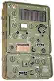
HF radio device AN/GRC-9
  The AN/GRC-9 radio device was produced in 1950 in the USA, and the Yugoslav Army received it as part of NATO aid in 1952. In the JNA it was the primary HF device in the infantry battalion for communication with the regiment–brigade. The AN/GRC-9 radio device was produced in 1950 in the USA, and the Yugoslav Army received it as part of NATO aid in 1952. In the JNA it was the primary HF device in the infantry battalion for communication with the regiment–brigade.
The receiver and transmitter frequency range from 2 MHz to 12 MHz, covering the upper part of the medium wave band in the 2–3 MHz portion. Operating modes: CW (telegraphy) and AM (amplitude-modulated telephony). It had a transmitter output power of 20W provided by a powerful directly-heated pentode 2E22. The transmitter and receiver are separate but housed in the same enclosure. Before establishing a link, the radio operator had to bring the receiver and transmitter frequencies to "zero" (the same value). The complete AN/GRC-9 was built in vacuum tube technology of American manufacture.
 It was powered from lead-acid accumulators of 6V, 12V or 24V via a dynamotor DY-88, or vibrator converter designated PE-237, but in the latter case output power was lower. Accumulator charging was performed by the generator RE-162S, which could also power the radio device in "buffer" connection with the accumulator. The set also included a hand generator GN-58-A-GY for topping up the accumulator. The receiver was powered by a dedicated battery designated BA-48. Most of these devices were repainted in JNA grey-olive color during their first major overhaul, and markings and controls were inscribed in Serbo-Croatian. Some American vacuum tubes were replaced with domestic equivalents. It was powered from lead-acid accumulators of 6V, 12V or 24V via a dynamotor DY-88, or vibrator converter designated PE-237, but in the latter case output power was lower. Accumulator charging was performed by the generator RE-162S, which could also power the radio device in "buffer" connection with the accumulator. The set also included a hand generator GN-58-A-GY for topping up the accumulator. The receiver was powered by a dedicated battery designated BA-48. Most of these devices were repainted in JNA grey-olive color during their first major overhaul, and markings and controls were inscribed in Serbo-Croatian. Some American vacuum tubes were replaced with domestic equivalents.
Used as a portable radio device, or was installed in the field vehicle Zastava AR-55V (the well-known jeep) together with the VHF radio device RUP-1(2), forming an HF/VHF system. The devices were operated via the Control box UK-6. Veteran radio-telegraphers held this device in extremely high regard and made it legendary. Origin: USA.. Learn more about this device at www.grc9.nl |
|
|
|
HF radio device RUP-4
  The RUP-4 radio device was produced at "Elektronska industrija" (Electronics Industry) in Niš in the early 1960s. It was designed on the model of the American radio device AN/GRC-9. It follows its block diagram completely, but more modern technological solutions were applied. Domestic electronic components, mostly produced at the same factory, were incorporated into the RUP-4. Infantry battalions of the JNA were equipped with the RUP-4, which served for radio communication with the regiment–brigade. The RUP-4 radio device was produced at "Elektronska industrija" (Electronics Industry) in Niš in the early 1960s. It was designed on the model of the American radio device AN/GRC-9. It follows its block diagram completely, but more modern technological solutions were applied. Domestic electronic components, mostly produced at the same factory, were incorporated into the RUP-4. Infantry battalions of the JNA were equipped with the RUP-4, which served for radio communication with the regiment–brigade.
Like the AN/GRC-9, the RUP-4 radio device operates in the frequency range from 2 MHz to 12 MHz with operating modes CW and AM. The transmitter output power is 20W, emitted by a double tetrode QQE03/20. The RUP-4's transmitter RD-2 and receiver RP-2 are separate. Transmitter RD-2 was built in domestic vacuum tube technology. The transmitter frequency was set with a variable oscillator (VFO). Unlike the transmitter, receiver RP-2 is fully transistorized (domestic germanium transistors from the Ei factory — Niš were used), ensuring lower power consumption and greater sensitivity and selectivity compared to the RT-77/GRC-9 receiver of the American AN/GRC-9 station. Likewise, the receiver frequency was tuned independently of the transmitter using a variable oscillator
 The RUP-4 radio device's transmitter was powered from a lead-acid accumulator of 6V or 12V via a transistor converter PT-5. The set also included a hand generator GR-1 for operation and accumulator charging. Transmitter consumption at full power was approximately 120W. The receiver was powered separately from the transmitter by two 4.5V dry batteries. The complete device set consisted of: transmitter RD-2, receiver RP-2, transceiver box, antennas (L-type wire, short and long whip antennas), converter PT-5, operating accessories (handset combination, headset, etc.), bags and covers for packing and carrying, and power sources. See the schematic. The RUP-4 radio device's transmitter was powered from a lead-acid accumulator of 6V or 12V via a transistor converter PT-5. The set also included a hand generator GR-1 for operation and accumulator charging. Transmitter consumption at full power was approximately 120W. The receiver was powered separately from the transmitter by two 4.5V dry batteries. The complete device set consisted of: transmitter RD-2, receiver RP-2, transceiver box, antennas (L-type wire, short and long whip antennas), converter PT-5, operating accessories (handset combination, headset, etc.), bags and covers for packing and carrying, and power sources. See the schematic.
 The RUP-4 radio device could be configured in two basic ways: The RUP-4 radio device could be configured in two basic ways:
First — transmitter RD-2 and receiver RP-2 are placed in the transceiver box, and the converter in a separate box; and
Second — transmitter RD-2 remains in the transceiver box, and converter PT-5 is placed instead of the receiver. Receiver RP-2 is then placed in a separate box. This arrangement is convenient when the transmitter needs to be separated from the receiving location for remote operation.
The RUP-4 radio device was used as a portable device, or was installed in the domestic field vehicle Zastava AR-55V together with the VHF radio device RUP-1(2), forming an HF/VHF radio-telephone system. In that configuration it was powered from a dedicated lead-acid accumulator of 12V/180Ah, also installed in the vehicle. It was "retired" at approximately the same time as the AN/GRC-9, in the 1980s. Origin: Yugoslavia. |
|
|
|
HF radio-receiver RP-2M
 The RP-2M radio receiver was one of the first domestic transistor radio devices. It was produced by "Elektronska industrija" (Electronics Industry) in Niš in the early 1960s, incorporating its germanium transistors. The device is intended for reception of unmodulated telegraphy (CW) and amplitude-modulated telephony (AM) in the frequency range from The RP-2M radio receiver was one of the first domestic transistor radio devices. It was produced by "Elektronska industrija" (Electronics Industry) in Niš in the early 1960s, incorporating its germanium transistors. The device is intended for reception of unmodulated telegraphy (CW) and amplitude-modulated telephony (AM) in the frequency range from  2 MHz to 12 MHz. The receive range is divided into three frequency sub-bands. It was powered by DC voltage from two 4.5V dry batteries. JNA communications units used this receiver as a standalone receiver or as part of the Small Command-Staff Vehicle (MKŠK) sets, most often for receiving the so-called "information wave". 2 MHz to 12 MHz. The receive range is divided into three frequency sub-bands. It was powered by DC voltage from two 4.5V dry batteries. JNA communications units used this receiver as a standalone receiver or as part of the Small Command-Staff Vehicle (MKŠK) sets, most often for receiving the so-called "information wave".
The RP-2M receiver is a double superheterodyne. The signal from the antenna is amplified in a two-stage RF amplifier and fed to the 1st mixer. The 1st mixer also receives the signal from the variable oscillator (VFO), which sets the operating frequency. The mixing product is the 1st intermediate frequency (IF) at 1780 kHz. The amplified signal in the 1st IF amplifier is fed to the 2nd mixer and mixed with the signal from a crystal oscillator at 1500 kHz. After mixing in the 2nd mixer, the signal enters the 2nd IF amplifier operating at 280 kHz. (Both IF amplifiers use conventional LC filters.) From the 2nd IF amplifier the signal enters the demodulator, and with the aid of a beat-frequency oscillator (BFO) crystal-controlled at 280 kHz an audio signal is generated, which is amplified in the audio-frequency amplifier and reproduced in headphones.
The receiver is housed in an aluminum enclosure with partial water-ingress protection. The receiver set consists of: the radio receiver, antennas (whip and wire), headphones, and packing and carrying accessories. Origin: Yugoslavia. |
|
|
|
HF radio device R-112
 The R-112 radio device was produced in the Soviet Union in 1950. It was included in the set of the Russian command armored personnel carrier BTR-50PU, which was procured for the armored units of the Yugoslav People's Army in the 1960s. The R-112 radio device was produced in the Soviet Union in 1950. It was included in the set of the Russian command armored personnel carrier BTR-50PU, which was procured for the armored units of the Yugoslav People's Army in the 1960s.
 It operated in the frequency range from 2.8 MHz to 4.99 MHz, with AM telephony and unmodulated telegraphy (CW). Frequency was set with two switches in steps of 10 kHz across 220 fixed working frequencies. Transmitter output power was 50W for AM and 90W for CW. The transmitter power amplifier incorporated four well-known Russian GU-50 pentodes. It was powered via two dynamotor converters designated UT-18A and UTK-250 by 26V DC from the vehicle's electrical network. The set included a short (4m) and a long (10m) telescopic whip antenna. It was built entirely in vacuum tube technology. Origin: USSR (Russia). It operated in the frequency range from 2.8 MHz to 4.99 MHz, with AM telephony and unmodulated telegraphy (CW). Frequency was set with two switches in steps of 10 kHz across 220 fixed working frequencies. Transmitter output power was 50W for AM and 90W for CW. The transmitter power amplifier incorporated four well-known Russian GU-50 pentodes. It was powered via two dynamotor converters designated UT-18A and UTK-250 by 26V DC from the vehicle's electrical network. The set included a short (4m) and a long (10m) telescopic whip antenna. It was built entirely in vacuum tube technology. Origin: USSR (Russia).
|
|
|
HF radio device R-130 (R-130M)
 The R-130 (R-130M) radio device was installed in Soviet command armored vehicles (T-55AK tank, BTR-50PK and 1V16 transporters), replacing the older Russian radio device R-112. The R-130 (R-130M) radio device was installed in Soviet command armored vehicles (T-55AK tank, BTR-50PK and 1V16 transporters), replacing the older Russian radio device R-112. It was imported together with the aforementioned armored vehicles. As in the USSR army, in the JNA it was intended for communication with higher commands. It was little used in the JNA because more modern domestic communications equipment surpassed it in the meantime. The R-130 was completed in two basic variants: the automotive variant (for installation in non-combat vehicles) and the tank variant, which was more common in the JNA. It was considered reliable and one of the best Soviet radio devices. It was imported together with the aforementioned armored vehicles. As in the USSR army, in the JNA it was intended for communication with higher commands. It was little used in the JNA because more modern domestic communications equipment surpassed it in the meantime. The R-130 was completed in two basic variants: the automotive variant (for installation in non-combat vehicles) and the tank variant, which was more common in the JNA. It was considered reliable and one of the best Soviet radio devices.
The R-130 radio device operated in the frequency range from 1.5 MHz to 10.99 MHz, divided into 10 sub-bands. The working frequency was set to 950 fixed frequencies (950 channels) with a spacing of 10 kHz. Its primary operating mode was SSB telephony, and it also supported AM telephony as well as CW and RTTY telegraphy. It could also be operated from a remote location using the TA-57 field telephone over a two-wire field line of up to 2 km . .
 Transmitter output power was 40W, emitted by two Soviet GU-50 pentodes. This power could be reduced to 20% if needed. Depending on the antenna, the device's range was from 50 km (4m whip antenna) to 350 km (symmetrical dipole and zenith radiation antenna). The device was powered by 26V DC from the vehicle's electrical network, with consumption of 13A during transmission and 3.5A during reception. It was built in vacuum tube technology and has 60 or 64 vacuum tubes. Transmitter output power was 40W, emitted by two Soviet GU-50 pentodes. This power could be reduced to 20% if needed. Depending on the antenna, the device's range was from 50 km (4m whip antenna) to 350 km (symmetrical dipole and zenith radiation antenna). The device was powered by 26V DC from the vehicle's electrical network, with consumption of 13A during transmission and 3.5A during reception. It was built in vacuum tube technology and has 60 or 64 vacuum tubes.
The basic device set consisted of: the transceiver, antenna unit, transistor converter, antenna sets, and operating accessories. The automotive variant set weighs approximately 90 kg, and the tank variant 120 kg. The modernized R-130M is completed with additional units enabling operation with a symmetrical dipole antenna and a zenith radiation antenna. Origin: USSR (Russia). Device description and photographs: Mixer.
|
|
|
|
HF radio-receiver R-311
 The R-311 shortwave radio receiver was produced in the Soviet Union after the end of World War 2. In the Yugoslav People's Army it was part of the BTR-50PU command armored personnel carrier's equipment, and was also found in some Soviet radio-teleprinter systems. The R-311 shortwave radio receiver was produced in the Soviet Union after the end of World War 2. In the Yugoslav People's Army it was part of the BTR-50PU command armored personnel carrier's equipment, and was also found in some Soviet radio-teleprinter systems.
The R-311 device is intended for reception of unmodulated telegraphy (CW) and amplitude-modulated (AM) telephony and telegraphy, in the frequency range from 1 MHz to 15 MHz. Frequency tuning was continuous, and the frequency range is divided into 5 sub-bands. It was built in vacuum tube technology as a single superheterodyne with an intermediate frequency of 465 kHz.
 It was powered from a steel accumulator designated 2-NKN-24 of 2.4V via the VP-3M2 vibrator converter. In an emergency, an 80V anode battery could be used instead of the accumulator and vibrator converter. The receiver was characterized by extremely low power consumption. When powered from the accumulator via the vibrator converter it consumed 1.1A (2.64W) with the dial illumination lamp on. Without the lamp, consumption was only 0.52A (1.25W). When powered from the anode battery, consumption was even lower. For a tube-based device with 8 vacuum tubes, dimensions 445×285×250 mm and weight 21 kg, this is truly impressive. It was powered from a steel accumulator designated 2-NKN-24 of 2.4V via the VP-3M2 vibrator converter. In an emergency, an 80V anode battery could be used instead of the accumulator and vibrator converter. The receiver was characterized by extremely low power consumption. When powered from the accumulator via the vibrator converter it consumed 1.1A (2.64W) with the dial illumination lamp on. Without the lamp, consumption was only 0.52A (1.25W). When powered from the anode battery, consumption was even lower. For a tube-based device with 8 vacuum tubes, dimensions 445×285×250 mm and weight 21 kg, this is truly impressive.
The receiver set, in addition to the power sources, consisted of headphones TA-56M, a 12m wire antenna, a 1.5m whip antenna, tools and spare parts. When operating from the BTR-50PU command armored personnel carrier, it used the shared 4m whip antenna. Origin: USSR (Russia). |
|
|
|
HF radio-receiver Kolins 51S-1 (Collins 51S-1)
 This legendary HF radio receiver by the American company "Collins" was purchased by the Yugoslav People's Army in the late 1960s. Our signalmen readily adopted it, and in JNA communications units it was used as a stationary communications receiver, or 4 Collins receivers were installed in the cargo cabin of the TAM-5000D field truck. That radio system was called the Collins Radio Reception Room and formed part of the receiving center of higher communications units. It also found significant application in electronic intelligence units, where in stationary listening centers it served as a receiver for monitoring foreign army radio traffic and controlling its own radio communications. This legendary HF radio receiver by the American company "Collins" was purchased by the Yugoslav People's Army in the late 1960s. Our signalmen readily adopted it, and in JNA communications units it was used as a stationary communications receiver, or 4 Collins receivers were installed in the cargo cabin of the TAM-5000D field truck. That radio system was called the Collins Radio Reception Room and formed part of the receiving center of higher communications units. It also found significant application in electronic intelligence units, where in stationary listening centers it served as a receiver for monitoring foreign army radio traffic and controlling its own radio communications.
The 51S-1 radio receiver was built in vacuum tube technology. The chassis was housed in what was at the time a modern perforated metal enclosure, with the front panel controls arranged clearly and logically. The 51S-1 receiver accepted CW, AM and SSB (LSB or USB) signals in the frequency range 200 kHz to 30 MHz (covering part of the long wave band, the complete medium wave band and short waves). This frequency range is divided into 30 sub-bands of 1 MHz each. The receive frequency was selected continuously with a variable oscillator — VFO. medium wave band and short waves). This frequency range is divided into 30 sub-bands of 1 MHz each. The receive frequency was selected continuously with a variable oscillator — VFO.
The receiver is superheterodyne. In the frequency range from 200 kHz to 7 MHz the receive signal is converted through three intermediate frequencies (1st IF: 14.5–15.5 MHz, 2nd IF: 3–2 MHz and 3rd IF: 500 kHz), while in the range from 7 MHz to 30 MHz the 1st IF (bandpass filter 14.5–15.5 MHz) is bypassed. The audio amplifier output impedance is from 8 to 600 ohms. The Collins 51S-1 was exceptionally sensitive in the range from 2 MHz to 30 MHz (MW: AM 15µV, SSB 3µV; HF: at 5 MHz AM < 3µV, SSB < 0.6µV) and highly selective (at −6 dB CW: 0.8 kHz, SSB: 2.4 kHz, AM: 5 kHz), while sensitivity and selectivity fell in the range from 200 kHz to 2 MHz.
The Collins 51S-1 was powered by AC voltage of 110V or 220V (115V AC–230V AC) at frequencies from 50 Hz to 400 Hz. Its power consumption was 125W and weight 11.8 kg.
In addition to the basic 51S-1 version, the JNA procured a smaller number of special versions of this receiver: 51S-1A (powered by 28V DC), 51S-1F (powered by 110/220V AC, intended for rack mounting), 51S-1AF (powered by 28V DC, rack mounting), and 51S-1B (with an adapter box enabling the use of standard military connectors). Origin: USA.
In addition to NATO member states, this receiver was sold to a larger number of other armies, and considerable material about it can be found on the internet. We recommend visiting the site: http://www.collinsradio.org/html/51s-1.html
Receiver description and photographs: Dragan Pavićević, YT1AR. |
|
|
|
HF radio device RUP-15
  A short-wave SSB low-power transceiver built at "RIZ" Zagreb in 1967, named transceiver PD-8, while the complete set was named RUP-15. It is intended to serve as the primary HF device in the infantry battalion command for communication with the regiment–brigade. It was built in transistor technology, with "RIZ" FET transistors used extensively. A short-wave SSB low-power transceiver built at "RIZ" Zagreb in 1967, named transceiver PD-8, while the complete set was named RUP-15. It is intended to serve as the primary HF device in the infantry battalion command for communication with the regiment–brigade. It was built in transistor technology, with "RIZ" FET transistors used extensively.
It operates in the frequency range from 2 MHz to 12 MHz, with operating modes CW, SSB and AM. Frequency is controlled by a direct-synthesis frequency synthesizer. Frequency is set with 4 decade switches in steps of 1 kHz. Transmitter output power is 15W PEP, provided by a transistor linear amplifier. Its intermediate frequency is quite low at 500 kHz, and its passband on receive and transmit is controlled by the SSB crystal filter of the "Mihailo Pupin" Institute. It is powered by 12V DC from an external source, or from a 12V lead-acid accumulator in buffer connection with a hand generator. The set includes a short, long and wire antenna.
 The RUP-15 was conceived as a portable device powered by its own silver-zinc accumulator. The said accumulator was never introduced into service, and the device had to be powered from an external voltage source. This seriously degraded this device, which is why it ended up as a low-power shortwave device in higher commands for internal communications. The RUP-15 was conceived as a portable device powered by its own silver-zinc accumulator. The said accumulator was never introduced into service, and the device had to be powered from an external voltage source. This seriously degraded this device, which is why it ended up as a low-power shortwave device in higher commands for internal communications.
It was installed in the Zastava AR-55V field vehicle together with the VHF radio device RUP-12, and in that configuration was named the Radio-Telephone System 15/12. Both devices were operated by a single radio operator via the control box UK-6. The devices were powered from a shared lead-acid accumulator 12V/70Ah housed in the vehicle cabin. Origin: Yugoslavia. |
|
|
|
HFradio-receiver RP-4
 In 1970, the "RIZ" factory from Zagreb, to shorten development time and reduce costs, used the RUP-15 radio device (its receiver block) as the basis for a short-wave receiver covering 2 MHz to 12 MHz for reception of CW, SSB, AM and RTTY signals. The receiver was installed in domestic radio-teleprinter systems and in receiving radio center systems of higher commands. It replaced the then-obsolete foreign-made receivers built in vacuum tube technology. In 1970, the "RIZ" factory from Zagreb, to shorten development time and reduce costs, used the RUP-15 radio device (its receiver block) as the basis for a short-wave receiver covering 2 MHz to 12 MHz for reception of CW, SSB, AM and RTTY signals. The receiver was installed in domestic radio-teleprinter systems and in receiving radio center systems of higher commands. It replaced the then-obsolete foreign-made receivers built in vacuum tube technology.
Externally it can easily be confused with the RUP-15 at first glance. Differences are visible only on the left side of the front panel, where a switch selects the band-pass filters added ahead of the input preamplifier (preselector), and a switch selects the receiver's passband . .
The modification aimed at increasing selectivity and resistance to strong signals with the aforementioned preselector and additional intermediate-frequency crystal filters (also manufactured by the "Mihailo Pupin" Institute). Filters were incorporated for each operating mode (CW, SSB, AM and RTTY). It was powered by an external 12V DC source (12V lead-acid or steel accumulator), or via a stabilized rectifier from 220V/110V AC.
 It was most commonly found in the RTpS-400 Radio-Teleprinter System or its "own system" — Reception Room 4 × RP-4. This consisted of 4 RP-4 receivers with associated telegraphy generators and teleprinters mounted in a cargo cabin on a TAM-5000 field truck, intended for receiving and dispatching messages at the receiving radio center. Dispatch went over a wire line to higher-power transmitters, which were separated by several kilometers so as not to betray the command post location. (An example of such remote control of a radio-teleprinter device from a distant location is shown in the image on the right.) Origin: Yugoslavia. It was most commonly found in the RTpS-400 Radio-Teleprinter System or its "own system" — Reception Room 4 × RP-4. This consisted of 4 RP-4 receivers with associated telegraphy generators and teleprinters mounted in a cargo cabin on a TAM-5000 field truck, intended for receiving and dispatching messages at the receiving radio center. Dispatch went over a wire line to higher-power transmitters, which were separated by several kilometers so as not to betray the command post location. (An example of such remote control of a radio-teleprinter device from a distant location is shown in the image on the right.) Origin: Yugoslavia.
|
|
|
HF radio device PRC-320L
 Officially, to overcome the shortage of low-power short-wave radio devices, the Yugoslav People's Army imported the British radio device PRC-320L from the well-known company PLESSEY. Critics said the device Officially, to overcome the shortage of low-power short-wave radio devices, the Yugoslav People's Army imported the British radio device PRC-320L from the well-known company PLESSEY. Critics said the device  was imported because the domestic RUP-15 radio device failed to meet the technical requirements for a portable low-power device due to problems with its internal silver-zinc accumulator. In any case, a very high-quality NATO device was imported, which was used in the JNA in reconnaissance units. Nevertheless, the majority of the imported PRC-320L devices were incorporated into the Small Command-Staff Vehicle (MKŠK) sets. was imported because the domestic RUP-15 radio device failed to meet the technical requirements for a portable low-power device due to problems with its internal silver-zinc accumulator. In any case, a very high-quality NATO device was imported, which was used in the JNA in reconnaissance units. Nevertheless, the majority of the imported PRC-320L devices were incorporated into the Small Command-Staff Vehicle (MKŠK) sets.
The PRC-320L HF radio device operated in the range from 2 MHz to 30 MHz (29.9999 MHz). Frequency was set with decimal switches in steps of 100 Hz. It operated  in CW, SSB and AM modes. Maximum transmitter output power was 30W PEP. It was powered by 24V DC from its nickel-cadmium accumulator, and the set also included a hand generator for topping up the accumulator. The antenna set consisted of a whip antenna and a wire dipole antenna. Origin: Great Britain. in CW, SSB and AM modes. Maximum transmitter output power was 30W PEP. It was powered by 24V DC from its nickel-cadmium accumulator, and the set also included a hand generator for topping up the accumulator. The antenna set consisted of a whip antenna and a wire dipole antenna. Origin: Great Britain. |
|
|
|
HF radio device RU-20 (PRC-515)
 The greatest success of Yugoslav defense industry was the purchase of a license from the Canadian company Rockwell-Collins for their PRC-515 device in the late 1970s. It was a very high-quality and very modern portable military HF low-power transceiver. The domestic device was produced by the "RIZ" factory from Zagreb and named Radio Device RU-20 (in foreign literature it is more often called "Yugoslav PRC-515"). Its purpose was the same as that of other HF tactical devices used in the JNA. Due to its ease of use and robust characteristics, it was most often encountered as the primary device of special units. The greatest success of Yugoslav defense industry was the purchase of a license from the Canadian company Rockwell-Collins for their PRC-515 device in the late 1970s. It was a very high-quality and very modern portable military HF low-power transceiver. The domestic device was produced by the "RIZ" factory from Zagreb and named Radio Device RU-20 (in foreign literature it is more often called "Yugoslav PRC-515"). Its purpose was the same as that of other HF tactical devices used in the JNA. Due to its ease of use and robust characteristics, it was most often encountered as the primary device of special units.
 Technical characteristics: Transmitter frequency range from 2 MHz to 30 MHz (29.9999 MHz), receiver from 500 kHz to 30 MHz. Working frequency set with BCD switches in steps of 100 Hz. Frequency is controlled by an indirect frequency synthesizer. Operating modes: SSB (LSB, USB), AM and CW. Transmitter output power 20W PEP, provided by a linear amplifier with automatic antenna tuner at the output. (Once the operating frequency and mode are set, pressing the key for a few seconds is sufficient for the device to automatically tune to the antenna.) Technical characteristics: Transmitter frequency range from 2 MHz to 30 MHz (29.9999 MHz), receiver from 500 kHz to 30 MHz. Working frequency set with BCD switches in steps of 100 Hz. Frequency is controlled by an indirect frequency synthesizer. Operating modes: SSB (LSB, USB), AM and CW. Transmitter output power 20W PEP, provided by a linear amplifier with automatic antenna tuner at the output. (Once the operating frequency and mode are set, pressing the key for a few seconds is sufficient for the device to automatically tune to the antenna.)
Power supply: NiCd accumulator 24V 1.8Ah. Operating temperature range from −54°C to +65°C. Antennas: whip and wire dipole antenna. The device set, in addition to the antennas (whip and wire dipole antenna AT-35), consisted of a frame and carrying bag, handset combination, head-worn telephone set, key, spare accumulator and hand generator for accumulator charging. The device is physically divided into three units (blocks) interconnected by fasteners. The longitudinally right block contains the complete  transceiver with an output power of 300 mW. The left block forms the linear power amplifier with automatic antenna tuner, and the power sources (accumulator and hand generator) are attached transversely from the rear. transceiver with an output power of 300 mW. The left block forms the linear power amplifier with automatic antenna tuner, and the power sources (accumulator and hand generator) are attached transversely from the rear.
The transceiver block is particularly interesting because it could serve as a solid foundation for a whole range of HF devices that the JNA needed at that time, as it was using radio-teleprinter systems based on vacuum tube technology. A partial start was made with the production of the RPrU-5/1 receiver, but the possibility of producing or importing a more powerful linear power amplifier (100W to 500W) with automatic antenna tuner and connecting it to the RU-20 transceiver block remained unexploited. This would have yielded a modern radio-teleprinter system, and with the connection of emerging computers, a "packet radio" system with moderate data transfer speeds. This did not happen due to a lack of financial resources on one hand, and on the other due to the indifference of responsible people in the military and the political changes taking place in the country. Later, in the early 1990s, spread-spectrum operating systems and frequency-hopping technology became relevant for military HF and VHF radio, and this device rapidly lost its relevance. The Republic of Croatia, based on this device, designed and produced for its own military needs an HF SSB radio transceiver with frequency hopping, the TRC-20H, whose image can be viewed here. Origin: Yugoslavia. |
|
|
| |
HF radio-receiver RPrU-5/1
The "RIZ" factory in Zagreb produced the RPrU-5/1 radio receiver in 1982 by utilizing the high-quality HF transceiver of the RU-20 radio device (which it also produced under a license obtained from the Canadian company Rockwell-Collins). The Yugoslav People's Army adopted the receiver, and it served as a universal short-wave radio receiver . .
The receiver was created by "emptying" the linear power amplifier block and installing in it a preselector with band-pass filters, a manual antenna matching unit, attenuator and rectifier for powering the receiver from 220V/110V AC. It must be admitted that this block was not executed to the technological level of the transceiver block, and much is lacking compared to the preselector of the RU-20 radio device. Instead of automatic functions, the antenna is manually matched here and sub-bands are manually selected.
Technical characteristics: Frequency range from 500 kHz to 30 MHz. Frequency is set in steps of 100 Hz. Operating modes: CW, AM and SSB (LSB or USB). Power supply: 10V to 32V DC or 220V/110V AC. Antennas are the same as for the RU-20: whip and wire dipole antenna AT-35, and other accessories are the same, adapted to the receiver function (without key, handset combination, etc.). Origin: Yugoslavia. |
|
|
|


