|
| |
Mobile radio systems consisted of two or more radio devices mounted in an all-terrain vehicle. In the JNA this was in principle one or more HF radio devices, alongside which VHF radio and telephone-telegraph devices were also found. The vehicle was equipped with a common power source (batteries, generator or both) and other equipment necessary for its integration within a communications center. The system was usually named after the main HF radio device. For example: Radio Receiving Station 4XRP-4 (four HF radio receivers RP-4 mounted on a TAM-5000 vehicle), Radio-teleprinter System RTpS-100 (HF radio-teleprinter device RTU-100 mounted in an AR-55 or Pinzgauer vehicle) . .
We would particularly highlight radio-teleprinter systems, as radio-teleprinter devices maintained communications between higher units and commands. Radio-teleprinter devices in the JNA consisted of medium and high-power HF radio devices, which in addition to the standard operating modes (CW, AM, SSB and FM) also offered RTTY (radio-teleprinter) operation. This was the primary mode of communication between higher units and commands.
RTTY (Radio Teleprinter Telegraphy) involves the exchange of information via teleprinter over a radio device. Since the teleprinter operates with direct current pulses, these must be transformed into a suitable alternating current form and then introduced into the transmitter's modulator. This is done by a special circuit or device called a telegraph generator (see telegraph transceiver TG-2). The telegraph generator uses the FSK (Frequency Shift Keying) method where the mark and space pulses of the teleprinter are converted into two alternating signals — tones (in the JNA, 1125 Hz and 1425 Hz were used). On reception, the process is reversed. |
| |
Tabular overview of mobile radio systems |
(clicking on a device designation allows quick navigation to its section on this page) |
| |
SYSTEM NAME |
DEVICES |
FREQUENCY RANGE |
OPERATING MODES |
POWER |
ORIGIN |
| |
|
|
1.5-12,5 MHz |
CW, AM |
50W |
USA |
|
1.5-18 MHz |
CW, AM |
- |
USA |
| |
|
HF RX/TX : PD-6 |
2-12MHz |
CW, AM, SSB, RTTY |
120W |
Yugoslavia |
| |
|
VHF RX/TX: RU-2/1 |
30-69.95MHz |
FM |
1.4W |
Yugoslavia |
| |
|
TX: R-140 |
1.5-29,9999MHz |
CW, AM, DSB, RTTY |
1000W |
SSSR (Russia) |
| RX: R-155P |
1.5-29,9999MHz |
CW, AM, DSB, RTTY |
|
SSSR (Russia) |
| RX: R-311 |
1-15MHz |
CW, AM |
|
SSSR (Russia) |
| VHF RX/TX: R-105 |
36-46.1MHz |
FM |
1W |
SSSR (Russia) |
| Relay: R-405P-T1 |
390-420MHz |
FM |
1,5W |
SSSR (Russia) |
| |
|
TX: PB-110, LP-123 |
1.6-29,9999MHz |
Tx/Rx: CW, MCW, AM, SSB, DSB, F1 |
1000W |
Yugoslavia |
| RX: RP-150 |
0,25-29,9999MHz |
|
Yugoslavia |
| |
|
HF RX/TX R-112 |
2.8-4.99MHz |
CW, AM |
90W |
SSSR (Russia) |
| VHF RX/TX R-123 |
20-51.5MHz |
FM |
20W |
SSSR (Russia) |
| |
|
VHF RX/TX R-105 (105U) |
36-46.1MHz |
FM |
1W (50W) |
SSSR (Russia) |
| VHF RX/TX R-113 |
20-22.375MHz |
FM |
16W |
SSSR (Russia) |
| HF RX/TX R-112 |
2.8-4.99MHz |
CW, AM |
90W |
SSSR (Russia) |
| RX: R-311 |
1-15MHz |
CW, AM |
|
SSSR (Russia) |
|
| |
Description of Mobile Radio Systems |
 |
Radio system SCR-193
Radio-telephony system SCR-193 was received by the Yugoslav Army as part of military aid provided by the USA following the political conflict between Yugoslavia and the Soviet Union in 1948. It is interesting to note that this aid was later rarely written about in either Yugoslavia or the West, as it suited no one. The fact is that the USA generously helped Yugoslavia with armament and equipment, from fighter aircraft and armored vehicles (remember Sherman tanks) to vehicles (jeeps, dodges, willys), artillery and more. Among other things, the JNA was equipped with American communications equipment. After this aid, it was better armed than some NATO members — a unique example during the Cold War for an army of a socialist state.
 The Radio-telephone system SCR-193 consisted of: HF transmitter BC-191, HF receiver BC-312-N or BC-348, antenna AN-24A or AT-5, power sources (ONAN generator providing 24V output and two lead batteries 12V/135Ah), work and transport box with mounting elements, two PTK-56 cable reels and ML-1 cable reel for remote operation, and other accessories. The Radio-telephone system SCR-193 consisted of: HF transmitter BC-191, HF receiver BC-312-N or BC-348, antenna AN-24A or AT-5, power sources (ONAN generator providing 24V output and two lead batteries 12V/135Ah), work and transport box with mounting elements, two PTK-56 cable reels and ML-1 cable reel for remote operation, and other accessories.
The devices were mounted in a Zastava AR-55-V 4x4 0.5T vehicle manufactured at the Zastava automobile factory in Kragujevac under Italian license, while the generator, lead batteries, PTK-56 cable reels, ML-1 cable reel and other set components were transported in a Zastava D-2 V semi-trailer with 0.5T capacity.
 HF radio-transmitter BC-191 was produced during World War II in the USA using vacuum tube technology. It operated in the frequency range of 1.5 MHz to 12.5 MHz, on CW and AM telephony. Transmitter output power: 75W/CW, 50W/AM. The operating frequency was set by a variable oscillator VFO or a quartz crystal-controlled oscillator; the operating range was divided into six frequency bands. The frequency band was changed by swapping the transmitter driver (so-called BC panels). The remaining driver panels were stored in the semi-trailer. It was powered via dynamotor converter BD-77 by 12V DC from a lead battery. The total power consumption of the radio system (transmitter and receiver) at full transmitter output was a maximum of 57A. High consumption was due to the low efficiency of the dynamotor and vibrator converters of that era for converting DC voltage into the high voltages needed to power vacuum tubes. HF radio-transmitter BC-191 was produced during World War II in the USA using vacuum tube technology. It operated in the frequency range of 1.5 MHz to 12.5 MHz, on CW and AM telephony. Transmitter output power: 75W/CW, 50W/AM. The operating frequency was set by a variable oscillator VFO or a quartz crystal-controlled oscillator; the operating range was divided into six frequency bands. The frequency band was changed by swapping the transmitter driver (so-called BC panels). The remaining driver panels were stored in the semi-trailer. It was powered via dynamotor converter BD-77 by 12V DC from a lead battery. The total power consumption of the radio system (transmitter and receiver) at full transmitter output was a maximum of 57A. High consumption was due to the low efficiency of the dynamotor and vibrator converters of that era for converting DC voltage into the high voltages needed to power vacuum tubes.
 HF radio-receiver BC-312-N was produced in 1943 by the "Farnsworth Television and Radio Corporation" of the USA. It covered the frequency range of 1.5 MHz to 18 MHz, divided into 6 bands. It enabled reception of CW and AM signals. The receiver was built with vacuum tubes as a single-conversion superhetrodyne with a low intermediate frequency of 470 kHz, typical for that era. It was powered via a dynamotor converter by 12V–14V DC from a lead battery. HF radio-receiver BC-312-N was produced in 1943 by the "Farnsworth Television and Radio Corporation" of the USA. It covered the frequency range of 1.5 MHz to 18 MHz, divided into 6 bands. It enabled reception of CW and AM signals. The receiver was built with vacuum tubes as a single-conversion superhetrodyne with a low intermediate frequency of 470 kHz, typical for that era. It was powered via a dynamotor converter by 12V–14V DC from a lead battery.
The Radio-telephone system SCR-193 (transmitter BC-191 and receiver BC-312-N) was powered by 12V–14V DC from a common lead battery via the BD-77 dynamotor converter.
Much more about this system can be found online, as it has been extensively written about and belongs to the legendary radio devices used by the USA and Allies in World War II and the Korean War. Origin: USA. |
|
 |
Radio-teleprinter system RTpS-100 (RTU-100/V)
The Radio-teleprinter system RTpS-100 is a medium-power HF transceiver produced by "Elektronska industrija" in Niš in 1967, adapted for field operating conditions. It was primarily intended for simplex RTTY (radio-teleprinter) transmission and reception. It represented the primary radio device in an infantry regiment-brigade and as an RTP device in higher commands. It was also installed in some types of Navy vessels. It was produced as a stationary device or installed in an all-terrain vehicle Zastava AR-55V with semi-trailer Zastava D-2V (0.5T capacity), and from the 1980s in a Pinzgauer 710K vehicle.

Technical Specifications of RTpS-100 (RTU-100/V) - frequency range: 2 MHz to 12 MHz; frequency was set by a variable oscillator (later the transceiver was modified and a frequency synthesizer replaced the VFO);
- vrste rada: nemodulisana telegrafija (CW), SSB (i to LSB) telefonija, AM telefonija i radio-teleprinterska telegrafija (RTTY);
- snaga transmittera: 120W za CW i RTTY, 150W za SSB i 40W za AM;
- telegraphy speed: up to 75 baud; frequency shift is determined by the telegraph transceiver TG-2 (in the new version UP-1);
- device range: with wire antenna AT-5 via surface wave up to 60 km on CW, SSB and RTTY, and up to 35 km on AM; via sky wave from 120 km to 400 km depending on radio wave propagation conditions;
- osetljivost receivera: za prijem CW, SSB i RTTY manje od 2µV, a za prijem AM telefonije 5µV.
- receiver selectivity: manually adjustable in steps; at 6 dB attenuation: 250 Hz, 700 Hz, 3000 Hz and 5000 Hz, controlled by crystal filters in the receiver's intermediate frequency.
- power supply: 220/110V 50Hz AC for all set components and 12V DC for receive-only operation. Total system power consumption approximately 1300W (with heater on).
- PD-6 transceiver power consumption: in "receive" mode 150W; in "transmit-receive" mode 340W on receive and 660W on transmit; in "receive" mode on batteries 90W.
- weight: complete system on Zastava AR-55V with Zastava D-2V semi-trailer weighs approximately 2200 kg.
Komplet RTpS-100 (RTU-100/V)
The RTpS-100 was designed in the mid-1960s during the transition from vacuum tube to transistor technology. Vacuum tube production at the "EI"  factory in Niš was at its peak, and the designers opted for them, so the transceiver contained only 3 transistors and 26 tubes. By the late 1970s it was considered outdated and the first modifications were made to extend its service life, although there was a view that it should be replaced with a more modern transistor-based solution. This never happened due to lack of funds and the political situation, so it remained in JNA service until its dissolution in 1991. factory in Niš was at its peak, and the designers opted for them, so the transceiver contained only 3 transistors and 26 tubes. By the late 1970s it was considered outdated and the first modifications were made to extend its service life, although there was a view that it should be replaced with a more modern transistor-based solution. This never happened due to lack of funds and the political situation, so it remained in JNA service until its dissolution in 1991.
 Broadly, this system can be divided into two variants. The first represented the solution from the early 1970s and its mass introduction into JNA equipment, when it was called Radio-teleprinter Device RTU-100/V and installed in the all-terrain vehicle Zastava AR-55/V with semi-trailer Zastava D-2V. The second, newer variant emerged after numerous modifications and replacement of set components with more modern solutions. The last modifications were made in the mid-1980s and it was designated Radio-teleprinter System RTpS-100/2. This version was installed in the Pinzgauer 710K vehicle. Broadly, this system can be divided into two variants. The first represented the solution from the early 1970s and its mass introduction into JNA equipment, when it was called Radio-teleprinter Device RTU-100/V and installed in the all-terrain vehicle Zastava AR-55/V with semi-trailer Zastava D-2V. The second, newer variant emerged after numerous modifications and replacement of set components with more modern solutions. The last modifications were made in the mid-1980s and it was designated Radio-teleprinter System RTpS-100/2. This version was installed in the Pinzgauer 710K vehicle.
Detaljniji opis obe ove varijante pogledajte na posebnoj strani. Kliknite na:
Description of the RTU-100/V and RTpS-100/2 set
|
|
|
Radio-teleprinter system R-140
 Due to the need for a high-power radio device for realizing mobile radio links between the strategic commands of the JNA, in the 1970s the Due to the need for a high-power radio device for realizing mobile radio links between the strategic commands of the JNA, in the 1970s the radio-teleprinter system R-140 was purchased from the Soviet Union (Russia). The system was deployed on two vehicles. The transmitter and receiver were installed in a Russian gasoline all-terrain truck ZiL-131 5t 6x6, while a second vehicle (in the JNA, a domestic all-terrain truck TAM-5000D 5t 4x4) housed the remote control unit designated VPU. The R-140 immediately entered the formation of the JNA signals regiments serving the Supreme Command and army commands. radio-teleprinter system R-140 was purchased from the Soviet Union (Russia). The system was deployed on two vehicles. The transmitter and receiver were installed in a Russian gasoline all-terrain truck ZiL-131 5t 6x6, while a second vehicle (in the JNA, a domestic all-terrain truck TAM-5000D 5t 4x4) housed the remote control unit designated VPU. The R-140 immediately entered the formation of the JNA signals regiments serving the Supreme Command and army commands.
  The RTpS R-140 was in service with most armies of the former Warsaw Pact and represented a robust but very complex high-power radio device requiring skilled and trained operators. In the Soviet Army, an officer-engineer was assigned as chief of this system, and with these systems they covered the entire territory of the USSR. In the JNA, this role was performed by a non-commissioned officer chosen from the ranks of top radio-teleprinter operators with strong radio-technical knowledge. The remaining crew consisted of soldier radio-teleprinter operators and 2 drivers. The RTpS R-140 was in service with most armies of the former Warsaw Pact and represented a robust but very complex high-power radio device requiring skilled and trained operators. In the Soviet Army, an officer-engineer was assigned as chief of this system, and with these systems they covered the entire territory of the USSR. In the JNA, this role was performed by a non-commissioned officer chosen from the ranks of top radio-teleprinter operators with strong radio-technical knowledge. The remaining crew consisted of soldier radio-teleprinter operators and 2 drivers.
The device operated in duplex mode, in the frequency range of 1.5 MHz to 30 MHz, via telephone and teleprinter telegraphy simultaneously on the lower (LSB) and upper (USB) sidebands. The telephone and telegraph signals were separated by appropriate filters. Classical AM telephony and unmodulated telegraphy (CW) could also be used. The transmit and receive frequencies were determined by frequency synthesizers in the transmitter driver and receiver, in steps of 100 Hz. Transmitter output power was 850W–1000W depending on the operating frequency, achieving a range of 1000 km to 2000 km. The system was built using vacuum tube and transistor technology, and powered by three-phase AC from a gasoline generator AB-4T-230 with 4 kW output (in the JNA by diesel generator ADP-15) or from the 220/380V mains. AM telephony and unmodulated telegraphy (CW) could also be used. The transmit and receive frequencies were determined by frequency synthesizers in the transmitter driver and receiver, in steps of 100 Hz. Transmitter output power was 850W–1000W depending on the operating frequency, achieving a range of 1000 km to 2000 km. The system was built using vacuum tube and transistor technology, and powered by three-phase AC from a gasoline generator AB-4T-230 with 4 kW output (in the JNA by diesel generator ADP-15) or from the 220/380V mains.
When acquiring the R-140 system, the JNA Communications Directorate did not purchase the original Russian vehicle (ZiL) for installing the remote control unit VPU, but instead had it installed in a domestic all-terrain 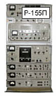 truck TAM-5000D. Further truck TAM-5000D. Further modifications were made to the Russian design. The gasoline generator AB-4T-230, housed in the ZiL-131 truck, was removed due to its unreliability and high fuel consumption and replaced by a domestic three-phase diesel generator ADP-15 with 15 kW output (fuel consumption 6 l/h), attached as a single-axle trailer to the ZiL-131. Also, the Russian Cyrillic teleprinters were replaced by Siemens T-100 models. Later, in the 1980s, for unification purposes, a modified domestic control unit UP-1A was installed in the R-140, allowing it to be operated the same way as domestic transmitters from the receiving room. modifications were made to the Russian design. The gasoline generator AB-4T-230, housed in the ZiL-131 truck, was removed due to its unreliability and high fuel consumption and replaced by a domestic three-phase diesel generator ADP-15 with 15 kW output (fuel consumption 6 l/h), attached as a single-axle trailer to the ZiL-131. Also, the Russian Cyrillic teleprinters were replaced by Siemens T-100 models. Later, in the 1980s, for unification purposes, a modified domestic control unit UP-1A was installed in the R-140, allowing it to be operated the same way as domestic transmitters from the receiving room.
 The R-140 set on the ZiL-131 consisted of: transmitter, receiver R-155P with receive antenna switch, control console PUR, radio-relay device R-405P-T1, HF receiver R-311, VHF transceiver R-105M, domestic teleprinter T-100, telephone set TA-57, voltage stabilizer and converter, various cables and a very wide spectrum of receiving and transmitting antennas. Erecting all antenna masts and antennas required an area larger than a football field (100 x 150 m). In addition to dipole and whip antennas, it is worth mentioning the broadband V-antenna for both receiving and transmitting, which operated on the principle of traveling waves and covered the entire HF range. Also distinctive is the AZI antenna (zenithal radiation antenna) mounted on the cabin roof, which radiated vertically. Using this antenna, with proper selection of operating frequencies, communications were achieved at shorter distances while in motion. The R-140 set on the ZiL-131 consisted of: transmitter, receiver R-155P with receive antenna switch, control console PUR, radio-relay device R-405P-T1, HF receiver R-311, VHF transceiver R-105M, domestic teleprinter T-100, telephone set TA-57, voltage stabilizer and converter, various cables and a very wide spectrum of receiving and transmitting antennas. Erecting all antenna masts and antennas required an area larger than a football field (100 x 150 m). In addition to dipole and whip antennas, it is worth mentioning the broadband V-antenna for both receiving and transmitting, which operated on the principle of traveling waves and covered the entire HF range. Also distinctive is the AZI antenna (zenithal radiation antenna) mounted on the cabin roof, which radiated vertically. Using this antenna, with proper selection of operating frequencies, communications were achieved at shorter distances while in motion.
  The remote control unit VPU on the TAM-5000D vehicle consisted of: control unit VPU with switching block, dispatcher accessories, 2 teleprinters T-100, radio-relay device R-405P-T1, mains rectifier, power generator, and line and mains cables. The remote control unit VPU on the TAM-5000D vehicle consisted of: control unit VPU with switching block, dispatcher accessories, 2 teleprinters T-100, radio-relay device R-405P-T1, mains rectifier, power generator, and line and mains cables.
Due to its high power, the system was separated into a transmitting center and controlled from the receiving radio center, where the VPU (remote control unit) was located. The VPU was connected to the R-140 by wire or via radio-relay device R-405P-T1. Operators in the VPU were able to conduct transmissions, change operating frequencies and select antennas on the R-140 transceiver via wire or radio-relay link.
The RTpS R-140 remained in JNA service until 1991, until the dissolution of former Yugoslavia and the JNA's abolition. Origin: USSR (Russia).
 Due to limited space on this site, the Radio-teleprinter System R-140 is not described in detail here. There are numerous websites from Eastern European countries about this device. We recommend some links: Due to limited space on this site, the Radio-teleprinter System R-140 is not described in detail here. There are numerous websites from Eastern European countries about this device. We recommend some links:
https://museum.radioscanner.ru,
https://museum.radioscanner.ru/r_140/r_140.html,
https://museum.radioscanner.ru/r_140/r_140m.html. |
|
|
Radio-teleprinter system RTpS-1KW
Due to the obsolescence of Soviet high-power radio-teleprinter systems, the need arose to replace them with more modern solutions, and in 1979 the Federal Secretariat for National Defense entrusted the development and production of a transistor RTpS with 1KW output power to Elektronska industrija "Pionir" from Zemun. EI "Pionir", seeking a partner for this far from easy task, entered into cooperation negotiations with the American company Rockwell Collins, which many — not without reason — consider the leader in military telecommunications device manufacturing. The negotiations concluded successfully. After completing the project and adopting multilayer circuit board production technology, on June 24, 1995, production began of the pride of Yugoslav radio industry — the Radio-teleprinter System RTpS-1KW.  Signals operators informally called it "our kilowatter" (naša kilovatka in Serbian). Signals operators informally called it "our kilowatter" (naša kilovatka in Serbian).
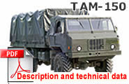
At that time, the RTpS-1KW represented a modern mobile HF radio-teleprinter system intended for strategic radio links at the army command — supreme command level in the HF range of 2–30 MHz, and was based on the family of dual-channel HF-80 radio devices produced under a license agreement with Collins. The system was installed in a military universal sheltered cabin K-30R transported on the all-terrain motor vehicle TAM-150BV 5t 6x6. If needed, the K-30R cabin could also be transported by rail, ship, helicopter and transport aircraft. The system was easy to operate, could be set up for work in less than 30 minutes, and crew comfort was ensured by the built-in air conditioning.
 Main technical specifications of the RTpS-1KW system: Main technical specifications of the RTpS-1KW system:
» Frequency range 2–30 MHz with ability to select 280,000 operating frequencies,
» Vrste rada: CW, MCW, AM, SSB, DSB i F1,
» Izlazna snaga transmittera 1KW PEP (zavisno od vrste rada),
» Automatic transmitter tuning in less than 6 seconds,
» Maximum telegraphy speed 200 Bd; frequency shift when operating with teleprinter 300 Hz (1125 Hz and 1425 Hz),
» Power supply by three-phase AC voltage 3x380/220V from generator ADP-15 or mains electricity,
» Total power consumption of all system devices under normal operating conditions 7.5 KVA,
» Total weight of the radio-teleprinter system including cabin, devices, installation components and accessories approximately 900 kg.
For a more detailed description of this complex RTpS, see the dedicated page. Click on:
Description of the Radio-teleprinter System RTpS-1KW
|
|
|
Command armored personnel carrier BTR-50PK & BTR-50PU
In the mid-1960s, the JNA acquired tracked amphibious command armored personnel carriers BTR-50PK and BTR-50PU from the USSR. The BTR-50PK was intended for command in lower armored units (mechanized or armored battalion), while the BTR-50PU was intended for command in higher armored and other units.
 Command Armored Personnel Carrier BTR-50PK was not originally a command vehicle in the USSR but a classical armored personnel carrier for transporting 20 soldiers or 2,000 kg of cargo, with a crew of 2: commander and driver. The JNA ordered a modified BTR-50PK which, in addition to the standard VHF radio device R-123, received an HF radio device R-112 for maintaining communications with the superior command (later replaced by the newer HF radio device R-130), and a staff work table was installed in the crew compartment. The vehicle was armed with an SGMB 7.62mm machine gun (combat load 1,250 rounds). The crew consisted of: vehicle commander, driver and radio operator. The vehicle served as a mobile headquarters of an armored or mechanized battalion. The commander was rarely transported in it, as his assigned position was in the command tank of the armored battalion (T-34K, T-55K or T-55AK), or in the command armored personnel carrier OT M-60 or the command infantry fighting vehicle BVP M-80A in JNA mechanized battalions. Command Armored Personnel Carrier BTR-50PK was not originally a command vehicle in the USSR but a classical armored personnel carrier for transporting 20 soldiers or 2,000 kg of cargo, with a crew of 2: commander and driver. The JNA ordered a modified BTR-50PK which, in addition to the standard VHF radio device R-123, received an HF radio device R-112 for maintaining communications with the superior command (later replaced by the newer HF radio device R-130), and a staff work table was installed in the crew compartment. The vehicle was armed with an SGMB 7.62mm machine gun (combat load 1,250 rounds). The crew consisted of: vehicle commander, driver and radio operator. The vehicle served as a mobile headquarters of an armored or mechanized battalion. The commander was rarely transported in it, as his assigned position was in the command tank of the armored battalion (T-34K, T-55K or T-55AK), or in the command armored personnel carrier OT M-60 or the command infantry fighting vehicle BVP M-80A in JNA mechanized battalions.
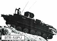 Command Armored Personnel Carrier BTR-50PU is intended to serve as a mobile headquarters of an operational unit (regiment, brigade, division and commands of equivalent rank). The JNA possessed the standard version. Its crew consists of 10 members: vehicle commander, driver, four radio operators, unit commander and three staff officers. Unlike the BTR-50PK, this vehicle is not armed. Command Armored Personnel Carrier BTR-50PU is intended to serve as a mobile headquarters of an operational unit (regiment, brigade, division and commands of equivalent rank). The JNA possessed the standard version. Its crew consists of 10 members: vehicle commander, driver, four radio operators, unit commander and three staff officers. Unlike the BTR-50PK, this vehicle is not armed.
 The vehicle is equipped with the following communications devices: VHF radio devices R-105, R-105U, R-113 (on later vehicles R-123); HF radio device R-112 (on later vehicles R-130); radio receiver R-311; radio-relay device R-403BM; intercom device R-120 (later replaced by R-124); 6 field telephones TAI-43 or TA-57 (2 portable and 4 in vehicle); field telephone exchange P-193A for 10 lines and 4 reels of 600m each of field telephone cable. The BTR-50PU set includes a generator AB-1-P/30 The vehicle is equipped with the following communications devices: VHF radio devices R-105, R-105U, R-113 (on later vehicles R-123); HF radio device R-112 (on later vehicles R-130); radio receiver R-311; radio-relay device R-403BM; intercom device R-120 (later replaced by R-124); 6 field telephones TAI-43 or TA-57 (2 portable and 4 in vehicle); field telephone exchange P-193A for 10 lines and 4 reels of 600m each of field telephone cable. The BTR-50PU set includes a generator AB-1-P/30  mounted on the engine-transmission compartment of the vehicle, used to power radio devices when the engine is not running. mounted on the engine-transmission compartment of the vehicle, used to power radio devices when the engine is not running.
Both carriers have the same engine (model V-6, four-stroke water-cooled diesel developing 240 hp at 1,800 rpm) and basic devices, differing only in details of the armored body (number and shape of roof hatches, etc.) and special equipment. Both vehicles have a maximum speed of 45 km/h (10 km/h in water), an operational range of approximately 250 km and a combat weight of approximately 14,300 kg. Origin: USSR (Russia).
Vehicle description and photographs: Vladimir Trendafilovski |
|
|
|


