|
| |
 The radio devices described on this page were used in the Yugoslav People's Army (JNA) for tactical low-power radio communications (0.1W–10W) over short distances in the VHF frequency range. VHF (Very High Frequency) covers frequencies from 30MHz to 300MHz. The defining characteristic of this range is that radio waves propagate nearly in straight lines — they do not reflect off the ionosphere, though they are partially reflected by objects. Communication between two devices is only possible over shorter distances where a so-called "line of sight" exists, and increasing the transmitter power does not significantly improve range. The radio devices described on this page were used in the Yugoslav People's Army (JNA) for tactical low-power radio communications (0.1W–10W) over short distances in the VHF frequency range. VHF (Very High Frequency) covers frequencies from 30MHz to 300MHz. The defining characteristic of this range is that radio waves propagate nearly in straight lines — they do not reflect off the ionosphere, though they are partially reflected by objects. Communication between two devices is only possible over shorter distances where a so-called "line of sight" exists, and increasing the transmitter power does not significantly improve range.
Because of this, jamming and interception of radio communications in this range is more difficult, and VHF links are still used in all armies today. The most common mode is FM (frequency modulation), or in modern implementations SSB (single-sideband — one sideband with suppressed carrier), while aviation has in some cases retained the classic AM (amplitude modulation). |
| |
Tabular overview of VHF radio devices |
(clicking on a device designation allows you to navigate quickly to that device on the page) |
| |
DESIGNATION
|
TYPE
|
FREQUENCY RANGE
|
MODE
|
TX POWER
|
ORIGIN
|
| |
|
RX |
52-60MHz |
FM |
- |
Yugoslavia |
| |
Torn.Fu.d2 |
TX/RX |
33.8-39.0MHz |
AM, CW |
1W |
Germany |
| |
A-7-A |
TX/RX |
27-32MHz |
FM |
1W |
USSR (Russia) |
| |
|
TX/RX |
52-60MHz |
FM |
0.3W |
Yugoslavia |
| |
|
TX/RX |
52-59.95MHz |
FM |
0.3W |
Yugoslavia |
| |
|
TX/RX |
38-54MHz |
FM |
0.5W |
Yugoslavia |
| |
|
TX/RX |
27-39MHz. |
FM |
0.5W |
Yugoslavia |
| |
|
TX/RX |
36-46.1MHz |
FM |
1W |
USSR (Russia) |
| |
|
TX/RX |
20-22.375MHz |
FM |
16W |
USSR (Russia) |
| |
|
TX/RX |
20-51.5MHz |
FM |
20W |
USSR (Russia) |
| |
|
TX/RX |
20-69.975 MHz |
FM |
30W |
Yugoslavia |
| |
|
TX/RX |
30-69.95MHz |
FM |
0.9-1.8W |
Yugoslavia |
| |
|
TX/RX |
30-69.95MHz |
FM |
1.4W |
Yugoslavia |
| |
|
TX/RX |
34-36.5MHz |
CW, SSB |
20W |
Yugoslavia |
| |
RT-20TM |
TX/RX |
34-36.995MHz |
MCW,SSB,FM |
20W |
Yugoslavia |
| |
|
TX/RX |
156-174MHz |
FM |
0.6-0.9W |
Yugoslavia |
| |
|
TX/RX |
149-154MHz |
FM |
0.6-0.9W |
Yugoslavia |
| |
UKT FM 66/17 |
TX/RX |
149-154MHz |
FM |
10W |
Yugoslavia |
| |
MRS 520-42/Ke |
TX/RX |
149-154MHz |
FM |
20W |
Yugoslavia |
|
| |
Description of VHF radio devices |
 |
| 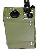 VHF radio-receiver RP-6 VHF radio-receiver RP-6
This device was not operated by radio operators but was intended as the primary radio device for the infantry section commander, through which he would receive orders and information. It operated in the range from 52MHz to 60MHz on five crystal-controlled channels with FM modulation. The headset cable serves as the antenna for this receiver. Also noteworthy, the device has no on/off switch — it is activated by a short-circuit plug in the headset connector when the headset is plugged into the receiver.
It was powered by a standard 9V battery. It was not widely adopted into JNA equipment because its main drawback was that it was receive-only. It was manufactured by RIZ Zagreb. Origin: Yugoslavia. |
|
|
 |
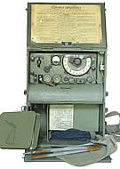
VHF radio device Torn.Fu.d2
The VHF radio device Torn.Fu.d2 entered Yugoslav Army service as war booty. It was produced in Germany in 1935 for the German ground forces, and there are records of it also being used by the Luftwaffe. In the Yugoslav Army it was used for tactical radio communications. The Torn.Fu.d2 transceiver supported amplitude- modulated telephony (AM) and unmodulated telegraphy (CW) in the frequency range from 33.8MHz to 39.0MHz, with an output power of 1W. At this power level, a range of 3km was achieved in telephony mode and up to 10km in telegraphy mode. The device was powered by DC from a single 2V battery (type 2B38) and two series-connected 90V anode batteries (type DIN1600). It was built using vacuum tube technology (see the electrical schematic). The transmitter had three tubes: two RV2P800 pentodes RV2P800 and one RL2T2 triode, and the receiver had six RV2P800 pentodes. modulated telephony (AM) and unmodulated telegraphy (CW) in the frequency range from 33.8MHz to 39.0MHz, with an output power of 1W. At this power level, a range of 3km was achieved in telephony mode and up to 10km in telegraphy mode. The device was powered by DC from a single 2V battery (type 2B38) and two series-connected 90V anode batteries (type DIN1600). It was built using vacuum tube technology (see the electrical schematic). The transmitter had three tubes: two RV2P800 pentodes RV2P800 and one RL2T2 triode, and the receiver had six RV2P800 pentodes.
The Torn.Fu.d2 was housed in two metal cases: one contained the transceiver weighing 17kg, and the other the batteries and accessories weighing 18.5kg. The device set also included a 2m whip antenna, which could be mounted directly on the device or separately on a small mast.
The Torn.Fu.d2 radio device did not remain in Yugoslav Army service for long. Shortly after World War II it was replaced by more modern American and domestic tactical VHF devices. Origin: Germany. |
|
|
|
VHF radio device A-7-A
 The VHF radio device A-7-A entered Yugoslav Army signals units as part of post-war aid from the "fraternal" Soviet Union to Yugoslavia. This device was developed after a design team led by Georgiy Trofimovich Shitikov received the assignment in 1938 to develop a portable VHF radio device. By late 1940 the radio device A-4 emerged. Development continued in parallel, and in 1941 the A-7 radio station was designed. Instead of AM The VHF radio device A-7-A entered Yugoslav Army signals units as part of post-war aid from the "fraternal" Soviet Union to Yugoslavia. This device was developed after a design team led by Georgiy Trofimovich Shitikov received the assignment in 1938 to develop a portable VHF radio device. By late 1940 the radio device A-4 emerged. Development continued in parallel, and in 1941 the A-7 radio station was designed. Instead of AM modulation (as used in the A-4), FM modulation was introduced — making it the first Soviet-produced FM radio device. The A-7 was adopted into service during the Battle of Stalingrad. Development continued (power consumption reduced by 30%, receiver sensitivity improved) and in 1944 the model A-7-A was introduced. In December 1944 the model A-7-B appeared. By the end of the war approximately 4,000 sets were being produced per month. modulation (as used in the A-4), FM modulation was introduced — making it the first Soviet-produced FM radio device. The A-7 was adopted into service during the Battle of Stalingrad. Development continued (power consumption reduced by 30%, receiver sensitivity improved) and in 1944 the model A-7-A was introduced. In December 1944 the model A-7-B appeared. By the end of the war approximately 4,000 sets were being produced per month.
The A-7-A was built using vacuum tube technology (see the electrical schematic). Technical characteristics: frequency range 27MHz to 32MHz, FM modulation, transmitter output power 1W, whip antenna. Range in open terrain was 7–8km, and in urban areas 3–4km. The transceiver, accessories, and power sources were stored in a wooden chest that served for both transport and operation. Weight without power sources was 15.5kg. Power supply: 2NKN-10 accumulator (2.4V) and two series-connected BAS-80 anode batteries (160V). The device was operated by a single radio-telephonist. chest that served for both transport and operation. Weight without power sources was 15.5kg. Power supply: 2NKN-10 accumulator (2.4V) and two series-connected BAS-80 anode batteries (160V). The device was operated by a single radio-telephonist.
After 1948 and the break in relations with the Soviet Union, the Yugoslav Army — faced with a shortage of spare parts for Soviet equipment — modified this station by replacing the original Russian vacuum tubes with American-made equivalents. Shortly thereafter the device was withdrawn from service and replaced by domestic tactical VHF radio stations. Origin: USSR (Russia). |
|
|
|
VHF radio device RUP-3
A VHF transceiver produced in the early 1960s by "RIZ" Zagreb. It was designed for short-range radio-telephony communications (0.5km to 3km depending on terrain). It served as the primary device of the infantry platoon commander  and was also used by members of other branches and services in the JNA. and was also used by members of other branches and services in the JNA.
 It operated in the range from 52MHz to 60MHz on five crystal-controlled channels with FM modulation, and an output power of 0.3W. In early production it was powered by two 9V lead-alkaline batteries or four 4.5V batteries, and later by two NiCd accumulators type 7ACH-1 at 8.4V/500mAh. The crystals — and thus the operating frequency — were rarely changed, as doing so required opening the device in a workshop and readjusting the transmitter output stage. It was built using domestically produced germanium transistors, and notably had no printed circuit board — components were soldered to lugs within modules, similar to the construction technique used with vacuum tubes. It operated in the range from 52MHz to 60MHz on five crystal-controlled channels with FM modulation, and an output power of 0.3W. In early production it was powered by two 9V lead-alkaline batteries or four 4.5V batteries, and later by two NiCd accumulators type 7ACH-1 at 8.4V/500mAh. The crystals — and thus the operating frequency — were rarely changed, as doing so required opening the device in a workshop and readjusting the transmitter output stage. It was built using domestically produced germanium transistors, and notably had no printed circuit board — components were soldered to lugs within modules, similar to the construction technique used with vacuum tubes.
The device set consisted of: the transceiver, AT-9 whip antenna made of steel strips, AT-10 wire antenna of 4m insulated copper braid for extended stationary range (included only in early production, later dropped as unnecessary), MK-2 handset combination, power sources, TB-5 carrying case, UP-1 carrying strap, and spare crystals in their box.
Origin: Yugoslavia. |
|
|
|
VHF radio device RUP-33
 A tactical VHF radio device produced by "RIZ" Zagreb in 1978, it represented a completely new design compared to the RUP-3. Like the RUP-3, it operated in the frequency range from 52MHz to 59.95MHz with FM modulation, but it featured a direct frequency synthesizer with channel selection via three rotary switches. Channel spacing was 50kHz. Output power remained the same A tactical VHF radio device produced by "RIZ" Zagreb in 1978, it represented a completely new design compared to the RUP-3. Like the RUP-3, it operated in the frequency range from 52MHz to 59.95MHz with FM modulation, but it featured a direct frequency synthesizer with channel selection via three rotary switches. Channel spacing was 50kHz. Output power remained the same  (0.3W), as did the power supply (two NiCd type 7ACH1 batteries at 8.4V/500mAh produced at the "Krušik" factory in Valjevo, or in an emergency four 4.5V batteries). (0.3W), as did the power supply (two NiCd type 7ACH1 batteries at 8.4V/500mAh produced at the "Krušik" factory in Valjevo, or in an emergency four 4.5V batteries).
Construction used printed circuit board technology, silicon and MOSFET transistors, and integrated circuits. A crystal filter from the "Mihajilo Pupin" Institute was installed in the receiver's intermediate-frequency amplifier, which improved the device's sensitivity and resistance to interference. Origin: Yugoslavia. |
|
|
|
VHF radio devices RUP-1, RUP-2, RUP-1B, RUP-2A and RUP-2B
 The first domestically produced radio devices, manufactured at the "Rudi Čajavec" factory in Banja Luka in 1958, intended for tactical VHF communications. RUP-1 and RUP-2 were based on the concept of the American The first domestically produced radio devices, manufactured at the "Rudi Čajavec" factory in Banja Luka in 1958, intended for tactical VHF communications. RUP-1 and RUP-2 were based on the concept of the American 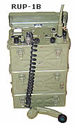 radio device BC-1000 (which was already in JNA service as part of military aid). They differed from each other only in frequency range. radio device BC-1000 (which was already in JNA service as part of military aid). They differed from each other only in frequency range.
The RUP-1 operated in the frequency range from 38MHz to 54MHz, and the RUP-2 from 27MHz to 39MHz. Mode of operation was FM telephony, with frequency set by a VFO (variable frequency oscillator). Output power was approximately 0.5W. They were powered from two "steel" alkaline accumulators (using potassium hydroxide as electrolyte) at 4.8V DC, through a vibrator converter PV-1 (RUP-1 and RUP-2 only) and a 20W transistor converter PT-1 (all versions) that provided the required DC voltages of 90V, 120V, and 150V. Alternatively a BAJ-70 dry battery could be used (providing 4.5V, 60V, and 90V DC). As with the BC-1000, the microphone and headphones were connected separately via 6.3mm jacks. They were built using American-made vacuum tube technology.
 In order to standardize domestic radio devices, a modification was made and "B" versions were produced (RUP-1B and RUP-2B). These differed from the "older" versions by having a standard military 7-pin In order to standardize domestic radio devices, a modification was made and "B" versions were produced (RUP-1B and RUP-2B). These differed from the "older" versions by having a standard military 7-pin  connector for the handset combination, while retaining the 6.3mm jack for headphones. A squelch circuit was added and several other minor changes were made. connector for the handset combination, while retaining the 6.3mm jack for headphones. A squelch circuit was added and several other minor changes were made.
The RUP-1(B) and RUP-2(A,B) devices were packed in three metal cases connected by fasteners: the upper case contained the device itself, the middle case the PT-1 voltage converter with two "steel" accumulators, and the lower case the microphone (or handset combination), headphones, cables, and accessories. Total set weight: 19.5kg. Origin: Yugoslavia. |
|
|
|
| VHF radio devices R-105, R-108 and R-109
  VHF devices imported together with Soviet radio-teleprinter systems and armored vehicles around 1960. Since the domestic radio device RUP-12 was produced in the same years and was technically a generation ahead, these devices did not find widespread use in the JNA. VHF devices imported together with Soviet radio-teleprinter systems and armored vehicles around 1960. Since the domestic radio device RUP-12 was produced in the same years and was technically a generation ahead, these devices did not find widespread use in the JNA.
They differ in frequency range (R-105: 36MHz to 46.1MHz, R-108: 28MHz to 36.5MHz, R-109: 21.5MHz to 28.5MHz). Output power is approximately 1W and modulation is FM. Frequency is set using a variable frequency oscillator.
 When connected to the Soviet UM-3 power amplifier, an output of 50W was achieved, provided by the well-known "Russian" GU-50 pentode. The R-105, R-108, and R-109 were built using miniature vacuum tube technology. The device set consisted of: the transceiver, a purpose-built whip antenna, handset combination and headphones, accessories, and power sources. They were powered by DC from "steel" alkaline accumulators rated 2.4V/22Ah, type KNP-20. Origin: USSR (Russia). When connected to the Soviet UM-3 power amplifier, an output of 50W was achieved, provided by the well-known "Russian" GU-50 pentode. The R-105, R-108, and R-109 were built using miniature vacuum tube technology. The device set consisted of: the transceiver, a purpose-built whip antenna, handset combination and headphones, accessories, and power sources. They were powered by DC from "steel" alkaline accumulators rated 2.4V/22Ah, type KNP-20. Origin: USSR (Russia).
|
|
|
|
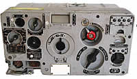
VHF radio device R-113
 A radio device produced in 1950 in the Soviet Union. It was imported as one of the communications devices in the set of the BTR-50PU armored personnel carrier, which served as a mobile command post in higher commands and as a command vehicle in armored units. It was also found in Soviet T-55 tanks in JNA service. It was designed for communications between armored vehicles — both stationary and on the move — using FM telephony in the frequency range from 20MHz to 22.375MHz. By frequency range it would belong to HF devices, but due to its role and the fact that communications were maintained via the ground wave component of the electromagnetic field, we have grouped it here with the other "tank" devices. A radio device produced in 1950 in the Soviet Union. It was imported as one of the communications devices in the set of the BTR-50PU armored personnel carrier, which served as a mobile command post in higher commands and as a command vehicle in armored units. It was also found in Soviet T-55 tanks in JNA service. It was designed for communications between armored vehicles — both stationary and on the move — using FM telephony in the frequency range from 20MHz to 22.375MHz. By frequency range it would belong to HF devices, but due to its role and the fact that communications were maintained via the ground wave component of the electromagnetic field, we have grouped it here with the other "tank" devices.
 Its frequency was controlled by a quartz oscillator across 96 fixed frequencies with a channel spacing of 25kHz. The transmitter output of 16W was provided by the then-renowned Russian GU-50 vacuum tube in the power amplifier stage. On moderately varied terrain it achieved a range of over 20km. The receiver was a superheterodyne with triple conversion, and the complete device was built using vacuum tube technology — 20 tubes of type 12ZhIL and one GU-50. It was powered via its own BP-2A dynamotor converter from the vehicle electrical system at 26V or 13V DC. The device was operated using a tank crew helmet with LEM-3 laryngophone and TA-56M headphones. Operation used a 4-section whip antenna of 4m total length. Origin: USSR (Russia). Its frequency was controlled by a quartz oscillator across 96 fixed frequencies with a channel spacing of 25kHz. The transmitter output of 16W was provided by the then-renowned Russian GU-50 vacuum tube in the power amplifier stage. On moderately varied terrain it achieved a range of over 20km. The receiver was a superheterodyne with triple conversion, and the complete device was built using vacuum tube technology — 20 tubes of type 12ZhIL and one GU-50. It was powered via its own BP-2A dynamotor converter from the vehicle electrical system at 26V or 13V DC. The device was operated using a tank crew helmet with LEM-3 laryngophone and TA-56M headphones. Operation used a 4-section whip antenna of 4m total length. Origin: USSR (Russia).
|
|
|
VHF radio device R-123M
 Another VHF device well known in armored units, as it could be found in Soviet armored vehicles. Signals personnel encountered it and worked with it from the BTR-50PU command armored personnel carrier, where it served for command and coordination radio communications between the commander and subordinate units, and between armored and infantry units. Another VHF device well known in armored units, as it could be found in Soviet armored vehicles. Signals personnel encountered it and worked with it from the BTR-50PU command armored personnel carrier, where it served for command and coordination radio communications between the commander and subordinate units, and between armored and infantry units.
The operating frequencies extended into the upper part of the HF range (20MHz to 51.5MHz), with FM modulation. It had 1,261 operating frequencies divided across two ranges: 20MHz to 35.75MHz and 35.75MHz to 51.5MHz. Channel spacing was 25kHz. Transmitter output power was 20W, achieving a range of 20km on moderately varied terrain. The device was operated via the R-124 intercom unit (BTR-50PU) using a tank crew helmet. It was designed for use with a 4m whip antenna, or a backup antenna of 3m copper conductor. It was powered via a BP-26 transistor converter from the vehicle's 26V DC electrical system. Transmit current draw was 9.6A, and receive up to 3A. Origin: USSR (Russia). frequencies divided across two ranges: 20MHz to 35.75MHz and 35.75MHz to 51.5MHz. Channel spacing was 25kHz. Transmitter output power was 20W, achieving a range of 20km on moderately varied terrain. The device was operated via the R-124 intercom unit (BTR-50PU) using a tank crew helmet. It was designed for use with a 4m whip antenna, or a backup antenna of 3m copper conductor. It was powered via a BP-26 transistor converter from the vehicle's 26V DC electrical system. Transmit current draw was 9.6A, and receive up to 3A. Origin: USSR (Russia). |
|
|
VHF radio device RUT-1
 During the development of domestic combat vehicles (armored personnel carriers and tanks), a need arose to equip them with domestic radio devices as well. For this purpose, in the early 1970s, "Rudi Čajavec" of Banja Luka produced a low-power VHF radio device and named it the RUT-1. Beyond its primary function (voice communications between combat vehicles) it also enabled internal communication among crew members, which is difficult to maintain by voice due to noise and vibration. The RUT-1 met the specified tactical and technical requirements and proved to be compact and durable, quickly earning praise from members of JNA armored units. During the development of domestic combat vehicles (armored personnel carriers and tanks), a need arose to equip them with domestic radio devices as well. For this purpose, in the early 1970s, "Rudi Čajavec" of Banja Luka produced a low-power VHF radio device and named it the RUT-1. Beyond its primary function (voice communications between combat vehicles) it also enabled internal communication among crew members, which is difficult to maintain by voice due to noise and vibration. The RUT-1 met the specified tactical and technical requirements and proved to be compact and durable, quickly earning praise from members of JNA armored units.
The RUT-1 operated with FM telephony in the frequency range from 20MHz to 69.975MHz. The operating frequency was controlled by a frequency synthesizer and set directly with 4 rotary switches in steps of 25kHz between channels (2,000 channels total). For rapid frequency changes, up to 10 channels could be pre-programmed using a programmer circuit, and switching between them was then done with a dedicated selector switch.  Full transmitter output power was 30W, reduced power 2W to 5W, and low power 0.1 to 0.2W. On flat terrain at full transmitter power, a range of up to 20km was achieved. Internal crew communication was maintained via an intercom supporting up to 5 participants, with maximum audio output of 1.2W. The primary power source was the vehicle's 26V DC electrical system (with variations from 22V to 30V). Full transmitter output power was 30W, reduced power 2W to 5W, and low power 0.1 to 0.2W. On flat terrain at full transmitter power, a range of up to 20km was achieved. Internal crew communication was maintained via an intercom supporting up to 5 participants, with maximum audio output of 1.2W. The primary power source was the vehicle's 26V DC electrical system (with variations from 22V to 30V).
 The RUT-1 radio device set consisted of the PD-9 transceiver, the main broadband AT-22 whip antenna in three sections of 3.55m total length (which could be shortened to two sections giving a length of 2.6m), the auxiliary AT-23 whip antenna of 1.5m, and the UMR intercom unit. The RUT-1 radio device set consisted of the PD-9 transceiver, the main broadband AT-22 whip antenna in three sections of 3.55m total length (which could be shortened to two sections giving a length of 2.6m), the auxiliary AT-23 whip antenna of 1.5m, and the UMR intercom unit.
 The intercom unit (UMR) consisted of the main control box UK-9, to which up to two PD-9 transceivers could be connected, and which contained the audio output amplifier for the intercom circuit. It also served for selecting the operating mode (internal network, first or second radio device) and routed DC power to the radio devices. The UMR also included five UK-8 control boxes to which five ŠM-1 helmets were connected; their function was to amplify the laryngophone signal (the throat microphone in the helmet) and to switch between internal communication and radio communication and vice versa. Additionally there was one UK-10 and two UK-11 control boxes with a full set of interconnecting cables. (See the connection diagram.) The intercom unit (UMR) consisted of the main control box UK-9, to which up to two PD-9 transceivers could be connected, and which contained the audio output amplifier for the intercom circuit. It also served for selecting the operating mode (internal network, first or second radio device) and routed DC power to the radio devices. The UMR also included five UK-8 control boxes to which five ŠM-1 helmets were connected; their function was to amplify the laryngophone signal (the throat microphone in the helmet) and to switch between internal communication and radio communication and vice versa. Additionally there was one UK-10 and two UK-11 control boxes with a full set of interconnecting cables. (See the connection diagram.)
The device was built using transistor technology. The transmitter is very stable and resistant to shock and vibration, with sufficient output power (30W), and both antennas are matched across the full frequency range. The receiver is highly sensitive, a superheterodyne with a first intermediate frequency of 10.7MHz whose bandwidth is controlled by a high-quality crystal filter from the "Mihailo Pupin" Institute, Belgrade. The second intermediate frequency is at 455kHz, where a ceramic filter from the same manufacturer is used. When the PD-9 transceiver was used outside the vehicle, a standard MK-1 handset combination could be connected in place of the UK-9 if needed. Origin: Yugoslavia.
|
|
Romanian VHF radio device R-1230 "UGAR"
We describe this radio device on our website because it is the Romanian variant of the VHF radio device RUT-1 manufactured by "Rudi Čajavec". The devices share the same external appearance, technical specifications, and accessories. It came about through the less well-known cooperation between the military radio industries of Romania and Yugoslavia. This military-technical 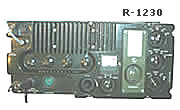 collaboration between the two countries in the 1970s is more widely known to the public through the "YUROM" project — the joint production of the ground-attack aircraft "Orao" ("IAR-93" — the Romanian designation). collaboration between the two countries in the 1970s is more widely known to the public through the "YUROM" project — the joint production of the ground-attack aircraft "Orao" ("IAR-93" — the Romanian designation).
The Romanian defence industry produced the VHF radio device R-1230 "UGAR" in the early 1980s. The Romanian Army used it to replace the Soviet tank radio device R-123 in 1982 on its T-55 tanks, TR-580, and TR-800. It was withdrawn from service in 2002. (Description and photo: Tudor, YO3HBN, Romania). |
|
|
| VHF radio device RUP-12
 The RUP-12 was produced at the "Rudi Čajavec" factory in Banja Luka in 1966, replacing the previous low-power tactical VHF radio stations BC-1000, RUP-1, RUP-2, and others built with vacuum tube technology. In JNA unit organization the RUP-12 became the primary radio device for infantry company commanders, and it was also used for VHF communications in higher commands, being installed in various radio-telephony, radio-teleprinter, and other systems. The RUP-12 was produced at the "Rudi Čajavec" factory in Banja Luka in 1966, replacing the previous low-power tactical VHF radio stations BC-1000, RUP-1, RUP-2, and others built with vacuum tube technology. In JNA unit organization the RUP-12 became the primary radio device for infantry company commanders, and it was also used for VHF communications in higher commands, being installed in various radio-telephony, radio-teleprinter, and other systems.
It operated in the frequency range from 30MHz to 69.95MHz using FM modulation across 800 channels. Frequency was controlled by a direct-synthesis frequency synthesizer and set with three rotary switches in steps of 50kHz. Transmitter output power ranged from 0.9 to 1.8W. It was powered from 12V DC. Initially it used a 12V/6Ah lead-acid accumulator or a BAJ-13.5 dry battery (13.5V). Later, power was supplied from a 7Ah NiCd accumulator made by "Krušik" Valjevo, or from an external 12V or 24V source via the PT-6 converter. Current consumption on receive was 85mA, and on transmit approximately 750mA. Weight of the portable set with accumulator: 12kg.
 The range of the RUP-12 depended on the antenna used and the deployment location. In flat terrain with the long whip antenna it was 8 to 12km. By connecting two devices with an appropriate adapter (a relay cable) and placing them on an elevated position, a signal relay station (repeater) could be formed, extending the range between the end users. Relaying was performed automatically or manually depending on the signal strength of the end participants, being activated by the squelch circuit signal. The range of the RUP-12 depended on the antenna used and the deployment location. In flat terrain with the long whip antenna it was 8 to 12km. By connecting two devices with an appropriate adapter (a relay cable) and placing them on an elevated position, a signal relay station (repeater) could be formed, extending the range between the end users. Relaying was performed automatically or manually depending on the signal strength of the end participants, being activated by the squelch circuit signal.
 The RUP-12 was built entirely with transistor technology, using predominantly domestically manufactured components. Receiver sensitivity was 1.2μV. The passband in the IF amplifier was controlled by a 10.7MHz crystal filter produced by the "Mihailo Pupin" Institute, providing good selectivity of ±15kHz from the center carrier frequency at 5dB attenuation. Transmitter operating frequency deviation from nominal was less than ±2kHz. The RUP-12 was built entirely with transistor technology, using predominantly domestically manufactured components. Receiver sensitivity was 1.2μV. The passband in the IF amplifier was controlled by a 10.7MHz crystal filter produced by the "Mihailo Pupin" Institute, providing good selectivity of ±15kHz from the center carrier frequency at 5dB attenuation. Transmitter operating frequency deviation from nominal was less than ±2kHz.
The portable RUP-12 set consisted of the PD-7 transceiver, power source (accumulator), TB-17 carrying bag, operating accessories (MK-1 handset combination and SL-1 headset), and three antennas (long whip AT-17, short whip AT-19, and AT-18 wire antenna on the travelling-wave principle). The vehicular set, in addition to all components of the portable set, also included the PT-6 transistor converter, AT-7 whip antenna, and other accessories for vehicle installation. Origin: Yugoslavia. |
|
|
|
VHF radio device RU-2 (RU-2/1, RU-2/2 and RU-2/2K)
 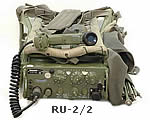 The RU-2 VHF radio device family (comprising models RU-2/1, RU-2/2, and RU-2/2K) was produced by "Rudi Čajavec" of Banja Luka in the late 1970s. The devices are externally identical to the RUP-12, as its enclosure, accessory set, and power sources were reused. The layout of controls on the front panel is also identical. In design, "Rudi Čajavec" followed the RUP-12 block diagram, but applied more modern technology — so it is fair to say this is an entirely new solution. The RU-2 VHF radio device family (comprising models RU-2/1, RU-2/2, and RU-2/2K) was produced by "Rudi Čajavec" of Banja Luka in the late 1970s. The devices are externally identical to the RUP-12, as its enclosure, accessory set, and power sources were reused. The layout of controls on the front panel is also identical. In design, "Rudi Čajavec" followed the RUP-12 block diagram, but applied more modern technology — so it is fair to say this is an entirely new solution.
  The difference lies in more modern construction technology. The most advanced semiconductors of the time were used (transistors and integrated circuits), partly imported and mostly domestically produced. For example, the first stage of the receiver — the VHF preamplifier — used a low-noise MOSFET transistor with selective tuned circuits controlled by varicap diodes and automatic gain control. The IF amplifier uses integrated circuits and a higher-quality crystal filter produced by the "Mihailo Pupin" Institute. The difference lies in more modern construction technology. The most advanced semiconductors of the time were used (transistors and integrated circuits), partly imported and mostly domestically produced. For example, the first stage of the receiver — the VHF preamplifier — used a low-noise MOSFET transistor with selective tuned circuits controlled by varicap diodes and automatic gain control. The IF amplifier uses integrated circuits and a higher-quality crystal filter produced by the "Mihailo Pupin" Institute.
The basic technical characteristics also resemble the RUP-12. Frequency range from 30MHz to 69.95MHz, 800 channels with 50kHz channel spacing, set with three rotary switches. Frequency is controlled by a direct frequency synthesizer. Transmitter output power is 1.4W, provided by a broadband transistor amplifier. It is a real shame that the designers did not find a way to raise the output power to 5–6W, as the enclosure space and power supply would allow it. Modulation is FM. Power supply is 12V DC from a 10KA-6 NiCd accumulator with a capacity of 7Ah, manufactured by "Krušik" Valjevo, or from an external source.
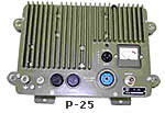  The RU-2 was designed for radio communications between infantry company and battalion level, but became the universal VHF device in the JNA. It served as a portable device or was installed into larger systems. A dedicated external power amplifier P-25 was developed for it, boosting output power to 20W. The RU-2/2K version could be connected to the KZu-63 speech encryption device. Origin: Yugoslavia. The RU-2 was designed for radio communications between infantry company and battalion level, but became the universal VHF device in the JNA. It served as a portable device or was installed into larger systems. A dedicated external power amplifier P-25 was developed for it, boosting output power to 20W. The RU-2/2K version could be connected to the KZu-63 speech encryption device. Origin: Yugoslavia.
|
|
|
|
| VHF radio device RT-20-TC6
  RT-20-TC6 VHF radio device was produced by the "Iskra" factory in Ljubljana in 1972. The device operated in the frequency range from 34MHz to 36.5MHz on 6 working channels controlled by quartz crystals. Mode of operation was SSB telephony and unmodulated telegraphy — CW. Full transmitter output power was 20W. It was powered by 12V DC from a 7Ah NiCd accumulator type 10KA-6 from the "Krušik" factory in Valjevo. RT-20-TC6 VHF radio device was produced by the "Iskra" factory in Ljubljana in 1972. The device operated in the frequency range from 34MHz to 36.5MHz on 6 working channels controlled by quartz crystals. Mode of operation was SSB telephony and unmodulated telegraphy — CW. Full transmitter output power was 20W. It was powered by 12V DC from a 7Ah NiCd accumulator type 10KA-6 from the "Krušik" factory in Valjevo.
 In the military it was principally used for communications with cooperating Territorial Defence units. From its introduction until its withdrawal from service it was not widely used in the JNA's mobile communications system, because all other devices in this frequency range used FM modulation — meaning mutual communication was only possible between two of these devices, or with compatible devices such as the "Iskra" models RT-1-T4, RT-1-T600, and RT-20TM, which were used in Territorial Defence units. Origin: Yugoslavia. In the military it was principally used for communications with cooperating Territorial Defence units. From its introduction until its withdrawal from service it was not widely used in the JNA's mobile communications system, because all other devices in this frequency range used FM modulation — meaning mutual communication was only possible between two of these devices, or with compatible devices such as the "Iskra" models RT-1-T4, RT-1-T600, and RT-20TM, which were used in Territorial Defence units. Origin: Yugoslavia.
|
|
|
|
VHF radio device RT-20TM (RUP-20)
 To revitalize its RT family of devices — which operate with SSB modulation on the tactical VHF band — "Iskra" of Ljubljana produced a VHF radio device designated RUP-20. To ensure To revitalize its RT family of devices — which operate with SSB modulation on the tactical VHF band — "Iskra" of Ljubljana produced a VHF radio device designated RUP-20. To ensure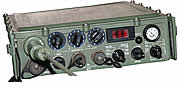 compatibility with the widely accepted tactical VHF devices such as the RUP-12, RUT-1, and RU-2/1, RU-2/2K, FM modulation capability was added. Iskra aimed to sell the RUP-20 to the military, but the JNA did not adopt it — it arrived too late, the JNA was already equipped with the RU-2/1, RU-2/2 (frequency range 30–70MHz) and RUT-1 (20–70MHz), and this device has a narrow frequency range of only 34MHz to 37MHz. compatibility with the widely accepted tactical VHF devices such as the RUP-12, RUT-1, and RU-2/1, RU-2/2K, FM modulation capability was added. Iskra aimed to sell the RUP-20 to the military, but the JNA did not adopt it — it arrived too late, the JNA was already equipped with the RU-2/1, RU-2/2 (frequency range 30–70MHz) and RUT-1 (20–70MHz), and this device has a narrow frequency range of only 34MHz to 37MHz.
Since the army did not purchase and adopt the RUP-20 (nor the other RT devices), "Iskra" gave this device a new designation: Radio device RT-20TM. It was then supplied to the Civil Defence, Territorial Defence, and the air surveillance, reporting and guidance system, which were already equipped with RT-20 TC6, RT-1 T-4, and RT-1 T-600 devices.
Technical specifications: Frequency range 34MHz to 36.995MHz. Frequency controlled by a synthesizer in steps of 5kHz (600 channels). Modes of operation: SSB  telephony, amplitude-modulated telegraphy (MCW), and FM telephony. Transmitter output power 20W (reduced: 6W and 2W). Receiver sensitivity: 1μV. Powered by 12V DC from a 12V/7Ah NiCd accumulator. The accumulator was mounted externally on the side opposite to that resting against the operator's back. Total set weight: 30kg. Origin: Yugoslavia. telephony, amplitude-modulated telegraphy (MCW), and FM telephony. Transmitter output power 20W (reduced: 6W and 2W). Receiver sensitivity: 1μV. Powered by 12V DC from a 12V/7Ah NiCd accumulator. The accumulator was mounted externally on the side opposite to that resting against the operator's back. Total set weight: 30kg. Origin: Yugoslavia. |
|
|
|
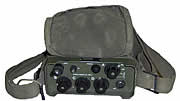
VHF radio device UKT FM 66/13
i UKT FM 66/13i
The UKT FM 66/13 and UKT FM 66/13i devices, from "Ei-Niš", factory Ei-Pionir, Zemun, were produced in the late 1960s and were intended for various users for maintaining VHF communications in the so-called radio-telephony band over short distances, with range extendable through the use of repeaters.
 Over the years of production it was made in several versions. The first two versions bore the designations UKT FM 66/13 and UKT FM 66/13i (the letter "i" denoted an external handset, while the 66/13 had a built-in speaker and microphone in the housing). Initially the antenna was a telescoping quarter-wave type, and the device was carried Over the years of production it was made in several versions. The first two versions bore the designations UKT FM 66/13 and UKT FM 66/13i (the letter "i" denoted an external handset, while the 66/13 had a built-in speaker and microphone in the housing). Initially the antenna was a telescoping quarter-wave type, and the device was carried 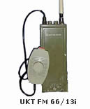 slung over the shoulder on a thin leather strap. Later it was fitted with a more practical shortened antenna, and a leather case was offered as part of the accessories, also worn over the shoulder. slung over the shoulder on a thin leather strap. Later it was fitted with a more practical shortened antenna, and a leather case was offered as part of the accessories, also worn over the shoulder.
Frequency range from 149MHz to 154MHz, or from 156MHz to 174MHz. Operation on 5 channels: 4 simplex and 1 semi-duplex (repeater). Channel spacing 25kHz (50kHz in early versions). Mode of operation: FM, transmitter output power 0.6 to 0.9W. Initially channels were numbered sequentially, later designated according to user nomenclature. The number of simplex and semi-duplex channels out of the total 5 could be varied to suit user requirements.
The technology is transistor-based, using germanium PNP transistors from SGS (IW9549, IW9374...), as well as AFY-12, AF124... transistors; only the transmitter output stage used NPN transistors 2N4427, 2N3553, or 2N3866. The transmitter operated on the principle of phase modulation of the crystal oscillator with frequency multiplication (here 24× with maximum deviation ±5kHz), while the receiver had a first intermediate frequency of 10.7MHz (initially 10MHz) and a second at 455kHz with classic LC IF amplifiers and a ceramic filter in the second IF stage.
They were powered by a 12V 450mAh NiCd accumulator manufactured by "Krušik" Valjevo. Initially the battery was built in and not user-replaceable. Charging was done via a connector on the front panel using the charger supplied with the device, meaning the device could not be used while charging. In later versions the accumulator became user-replaceable, and charging was done using a group battery charger. Origin: Yugoslavia. |
|
|
|
VHF radio device UKT FM 66/17
The radio device UKT FM 66/17 is also a product of "Ei-Niš", Ei-Pionir factory, Zemun, produced in the 1960s. It was designed for radio communications in the VHF radio-telephony band (146MHz–174MHz). This frequency range was allocated to  users requiring short-range radio communications and was divided into several sub-bands. The Ei-Pionir factory offered the UKT FM 66/17 to these users. It was produced in multiple versions depending on application (mobile or stationary) and user (military, police, utilities and other services, enterprises, institutions — it could even be found in agricultural combine harvesters). It is fair to say this is the radio device produced in the greatest quantities and most widely used in the former Yugoslavia. It was also the first fully solid-state European VHF 10W radio device powered directly from a 12V vehicle electrical system. Before it, only the Danish firm STORNO produced a solid-state device powered from a vehicle installation — at +24V. users requiring short-range radio communications and was divided into several sub-bands. The Ei-Pionir factory offered the UKT FM 66/17 to these users. It was produced in multiple versions depending on application (mobile or stationary) and user (military, police, utilities and other services, enterprises, institutions — it could even be found in agricultural combine harvesters). It is fair to say this is the radio device produced in the greatest quantities and most widely used in the former Yugoslavia. It was also the first fully solid-state European VHF 10W radio device powered directly from a 12V vehicle electrical system. Before it, only the Danish firm STORNO produced a solid-state device powered from a vehicle installation — at +24V.
The Yugoslav People's Army equipped a large number of its vehicles with this device and also used it as a stationary unit. A special telephone interface could be added to the stationary version, enabling connection to the telephone network. By deploying repeater stations (e.g., RRS/FRS 420-4 from the same manufacturer), it formed a  radio-telephony network covering the entire state territory and integrated this network into its communications system. This radio network was widely used in peacetime, but communications doctrine did not consider it significant in wartime as it is extremely vulnerable to the enemy's electronic and combat action. Approximately 500 UKT FM 66/17 units and about 40 RRS/FRS 420-4 repeaters were adapted for use with an external speech protection device, increasing resistance to electronic reconnaissance. These units were designated UKT-FM 66/17K (repeater RRS/FRS 420-4K), with the external speech encryption device being the KZu-64, also manufactured at the Ei-Pionir factory in Zemun. radio-telephony network covering the entire state territory and integrated this network into its communications system. This radio network was widely used in peacetime, but communications doctrine did not consider it significant in wartime as it is extremely vulnerable to the enemy's electronic and combat action. Approximately 500 UKT FM 66/17 units and about 40 RRS/FRS 420-4 repeaters were adapted for use with an external speech protection device, increasing resistance to electronic reconnaissance. These units were designated UKT-FM 66/17K (repeater RRS/FRS 420-4K), with the external speech encryption device being the KZu-64, also manufactured at the Ei-Pionir factory in Zemun.
The technical specifications presented here relate to the "military" version of the UKT FM 66/17. Devices for other users differed mainly in frequency range and number of channels. Over time Ei-Pionir also made modifications, and those devices were designated differently — hence designations such as UKT FM 66/18 and MRS 320-xx (e.g., the 22-channel MRS 320-22). Devices for the police were fitted with an ISP module conforming to the CCIR 70 standard for automatic identification and selective calling of participants. This was also done for other customers of this device.
 The UKT FM 66/17 operated using FM telephony in simplex or semi-duplex mode in the frequency range from 149MHz to 154MHz. The frequency was selected by a switch across 22 channels. Adjacent channel spacing was 25kHz, and the maximum deviation of the FM signal was ±5kHz. The transmitter radiated 10W output power, and the receiver had an input sensitivity better than 0.6μV. Audio output power in the speaker was 1W. It was powered from the vehicle accumulator at 12V DC. When used as a stationary unit it was powered from a rectifier (variously designated). Transmit current draw was 2.3A, and on receive 700mA at 1W audio output. The UKT FM 66/17 operated using FM telephony in simplex or semi-duplex mode in the frequency range from 149MHz to 154MHz. The frequency was selected by a switch across 22 channels. Adjacent channel spacing was 25kHz, and the maximum deviation of the FM signal was ±5kHz. The transmitter radiated 10W output power, and the receiver had an input sensitivity better than 0.6μV. Audio output power in the speaker was 1W. It was powered from the vehicle accumulator at 12V DC. When used as a stationary unit it was powered from a rectifier (variously designated). Transmit current draw was 2.3A, and on receive 700mA at 1W audio output.
The entire device was built using transistor technology. As with the UKT FM 66/13, the transmitter used phase modulation of the crystal oscillator, and frequency multiplication (24×) was used to obtain the required deviation and operating frequency. The resulting FM signal was amplified in a transistor power amplifier and sent to the antenna. The receiver is a dual-conversion superheterodyne with a first intermediate frequency of 10.7MHz with a classic transistor LC IF amplifier, and a second at 455kHz. Selectivity at this IF stage is controlled by a ceramic filter. The receive frequency was controlled by a quartz oscillator whose frequency, after multiplication (3×), was lower by the value of the first IF (10.7MHz). The basic device set consisted of: the transceiver, microphone, speaker, antenna, and antenna lead-in. Origin: Yugoslavia. (24×) was used to obtain the required deviation and operating frequency. The resulting FM signal was amplified in a transistor power amplifier and sent to the antenna. The receiver is a dual-conversion superheterodyne with a first intermediate frequency of 10.7MHz with a classic transistor LC IF amplifier, and a second at 455kHz. Selectivity at this IF stage is controlled by a ceramic filter. The receive frequency was controlled by a quartz oscillator whose frequency, after multiplication (3×), was lower by the value of the first IF (10.7MHz). The basic device set consisted of: the transceiver, microphone, speaker, antenna, and antenna lead-in. Origin: Yugoslavia. |
|
|
|
VHF radio device MRS 520-42/Ke
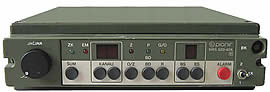 In 1985, the Ei-Pionir factory in Zemun entered production of dedicated VHF/UHF transceivers of the family designated MRS-500/Ke. These transceivers were conceived as system-oriented devices to provide a basic radio device capable of meeting requirements in all configurations encountered in military, police, and other professional networks. In 1985, the Ei-Pionir factory in Zemun entered production of dedicated VHF/UHF transceivers of the family designated MRS-500/Ke. These transceivers were conceived as system-oriented devices to provide a basic radio device capable of meeting requirements in all configurations encountered in military, police, and other professional networks.
 For the needs of the Yugoslav People's Army, EI-Pionir began production in 1991 of vehicular VHF radio devices MRS-520V/Ke for ground forces and MRS-520M/Ke for the navy. The devices were of robust and reliable construction, designed for operation from a motor vehicle or as a stationary unit under the most demanding operating conditions. They featured a built-in interface for connecting the external speech encryption device KZu-64. Instead of a standard handset, a standard dynamic microphone Mi-2 was used, and all controls from the KZu-64 were transferred to the front panel of the MRS-520V/Ke. For the needs of the Yugoslav People's Army, EI-Pionir began production in 1991 of vehicular VHF radio devices MRS-520V/Ke for ground forces and MRS-520M/Ke for the navy. The devices were of robust and reliable construction, designed for operation from a motor vehicle or as a stationary unit under the most demanding operating conditions. They featured a built-in interface for connecting the external speech encryption device KZu-64. Instead of a standard handset, a standard dynamic microphone Mi-2 was used, and all controls from the KZu-64 were transferred to the front panel of the MRS-520V/Ke.
The version delivered to the Army Ground Forces (KoV) was designated MRS 520-42/Ke. It operated with FM telephony in simplex mode (16 channels), semi-duplex (34 channels), and inverted semi-duplex (33 channels) in the range from 149MHz to 154MHz (the naval version also included International Maritime channels). Frequency was controlled by a synthesizer. Transmitter output power was 20W.
It was powered from the vehicle accumulator at 12V DC, or in the case of a 24V vehicle electrical system via a 24V/12V voltage converter designated BN-24/12-10. When used as a stationary unit it was powered from the 220V/50Hz mains via a stabilized 13.5V/6A rectifier designated SIP-500, which also served as a battery charger. This unit was later modified into the SIP-500 (6+6)Z (stabilizer 6A, battery charger 6A, with built-in speaker). For powering the MRS-520M/Ke on navy vessels from a 24V DC ship system or from a 220V/50Hz supply, the rectifier-converter version PIS-500 (6+6)Z was used. Origin: Yugoslavia.
More information about this device family can be found on the official website of the factory: Ei Pionir UKT d.o.o - Zemun. |
|
|
|
|
|


 The radio devices described on this page were used in the Yugoslav People's Army (JNA) for tactical low-power radio communications (0.1W–10W) over short distances in the VHF frequency range. VHF (Very High Frequency) covers frequencies from 30MHz to 300MHz. The defining characteristic of this range is that radio waves propagate nearly in straight lines — they do not reflect off the ionosphere, though they are partially reflected by objects. Communication between two devices is only possible over shorter distances where a so-called "line of sight" exists, and increasing the transmitter power does not significantly improve range.


